Gas leakage detecting device and detecting method thereof

A gas leak detection, gas technology, applied in the measurement device, by detecting the appearance of fluid at the leak point, testing the fluid tightness, etc., can solve the problems of inapplicable detection, low helium leakage, and reduced sensitivity, etc., to achieve Effect of improving gas collection ability, improving detection efficiency, and improving sensitivity

Active Publication Date: 2018-06-29
北京临近空间飞艇技术开发有限公司
11 Cites 13 Cited by

AI-Extracted Technical Summary

Problems solved by technology

Relevant foreign units have used mass spectrometry equipment to carry out related airship air leak detection tests, such as Google balloons and the American HiSentine high-altitude airship. Although they have certain effects, there are the following problems: the efficiency is very low when working at high altitudes; When materials are damaged (especially thin-film materials), the pressure and load-bearing capacity of the boat bag is limited. Under low pressure, the leakage of helium g...

Method used

(2) gas collection function, robot sucker has negative pressure adsorption function, simultaneously it is used as skin surface gas collection device, and the combination of non-contact blowing and gas collection unit realizes the fast gas collection of portable mass spectrometry equipment.
(4) Realize maximum detection area as far as possible under minimum path, realize fast detection, and prevent missed detection.
The detection device of the present embodiment realizes the negative pressure adsorption (also can adopt internal and external equipment to carry out magnetic adsorption) of flexible sucker on skin by vacuum pump inhalation, collects gas by blowing and gas collection unit, then utilizes mass spectrometry equipment Detect the change of helium concentration in the pipeline, and realize the functions of rapid detection, positioning, evaluation and recording of the skin gas leakage location. The operation is simple, the detection accuracy is high, the reaction time is fast, and the leak rate can be quantified. It is suitable for the rapid detection and positioning of the airtightness of large flexible structural containers, and can ...

Abstract

The invention provides a gas leakage detecting device and a detecting method thereof. The gas leakage detecting device and the detecting method thereof are capable of performing high-efficiency and high-sensitivity detection on gas leakage of an airtight vessel at high altitude and are applicable to rapid detection of airtightness and rapid positioning of a large flexible structural vessel. The device is characterized in that a creeping and positioning assembly is used for carrying a mass spectrometer; a single leaking point of an airship is quantified and positioned at high altitude by adopting a tracer gas method, so that the detection can be quickly and efficiently carried out; in addition, a vacuum pump is used for rapidly pumping gas, thus gas in a certain volume can be concentrated and stored in a vacuum chamber within the shortest time, and as a result, the gas collecting capacity is improved; the mass spectrometer is used for sampling and detecting concentrated and mixed gas inthe vacuum chamber by utilizing a circulating fan, and thus the equipment detection efficiency is improved. According to the device, the gas is collected by adopting an injection and gas collecting unit; compared with a general gas collecting device, an injection hole is added, so that the detection sensitivity is improved; a chuck body is used for adsorbing a detected target under negative pressure as well as absorbing gas.

Application Domain

Technology Topic

Image

  • Gas leakage detecting device and detecting method thereof
  • Gas leakage detecting device and detecting method thereof
  • Gas leakage detecting device and detecting method thereof

Examples

  • Experimental program(2)

Example Embodiment

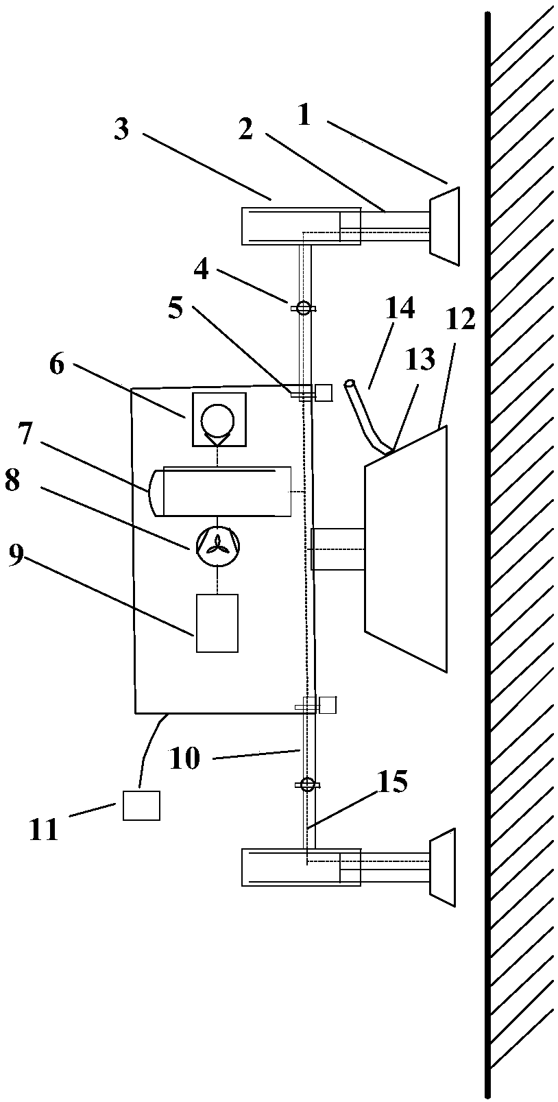
[0038] Embodiment 1: This embodiment provides a gas leak detection device, which uses the tracer gas method to quantify and locate a single leak point of the airship, and is powered by an external power supply 11. The detection device includes a detection component and a crawling positioning component;
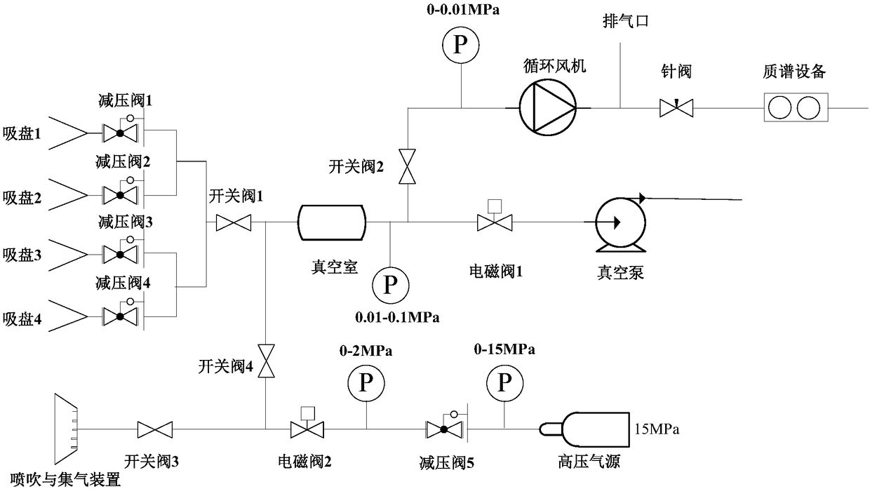
[0039] The detection component is used to detect airship skin defect gas leakage, including injection and gas collection unit 12, vacuum pump 6, vacuum chamber 7, circulation fan 8, mass spectrometry equipment 9, high-pressure gas source pipeline 14, gas collection pipe Road 15 and the control valve;
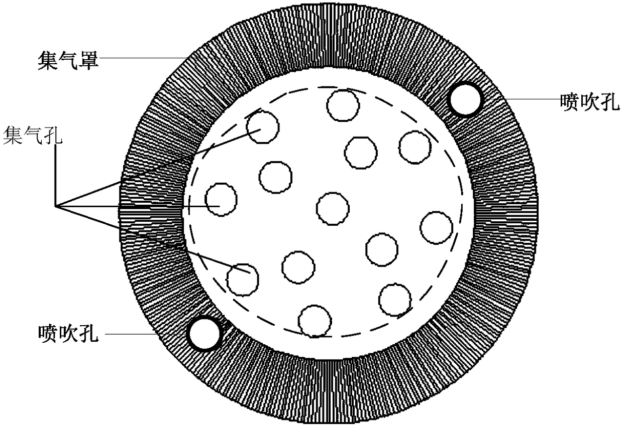
[0040] Wherein, the injection and gas collection unit 12 includes a gas collection hood and a high-pressure gas source; one end of the gas collection hood is provided with a gas collection hole for collecting gas, and the other end is connected to the inlet end of the vacuum chamber 7 through a switch valve IV, and the gas collected by the gas collection hole The gas enters the vacuum chamber 7 through the gas collecting hood.
[0041] The blowing and gas collection unit 12 plays an important role in the whole device. The schematic diagram of the end where the gas collection hole of the gas collection hood is located is shown in figure 2shown. It is the main equipment for external gas inhalation. In order to ensure a sufficient area to be detected under the minimum path, the gas collection port of the injection and gas collection unit 12 should be as large as possible. However, if the gas collection port is large, the space in the gas collection hood will become larger, and the efficiency of inhalation through a single pipeline will be reduced. Different positions (i.e. the air collection hole array) inhale at the same time to speed up the inhalation speed. In the case of a large leak detection area, it is ensured that every point in the air collection hood can quickly enter the vacuum chamber through the air intake pipeline. And if the load permits, a vacuum chamber and mass spectrometry equipment connected to the gas collection hole can be added, which is suitable for the rapid detection and positioning of the airtightness of large containers, and meets the requirements for airship skin defect detection.
[0042] Another function of the injection and gas collection unit 12 is to inject and dilute the background gas to ensure that the helium leaked from the airship occupies a certain concentration ratio in the outside air, so that the abnormality of helium can be accurately detected through the difference in concentration. Injection holes 13 are provided on the surface where the air collection holes of the gas collection hood are located, and the injection holes 13 are connected to the high-pressure air source through the high-pressure air source pipeline 14 provided with a solenoid valve II and a pressure reducing valve V. The stored gas is nitrogen or pure air. The injection and dilution of the background gas are realized through the gas injection pipeline system, which is mainly composed of on-off valve III, solenoid valve II, pressure reducing valve V and high-pressure gas source (nitrogen gas source is used in this embodiment). In the gas injection pipeline, an external high-pressure gas source is used to realize the function of diluting and blowing off the concentration of the gas to be detected in the detection background. The function of the pressure reducing valve V is to reduce the pressure of the high-pressure gas source. The high-pressure gas source is generally at 15MPa. The actual injection , the pressure needs to be reduced to within 2MPa. In order to ensure the independent controllability of the pipeline, the on-off valve III is designed to separately control the gas collection pipeline at the inlet. close.
[0043] The outlet end of the vacuum chamber 7 is connected to the vacuum pump 6 through the solenoid valve I, and the vacuum pump 6 is used to vacuumize the vacuum chamber 7 before gas collection; the outlet end of the vacuum chamber 7 is connected to the circulation fan 8 through the switch valve II, and the circulation fan 8 Connect the mass spectrometry device 9 through a pipeline provided with a needle valve, and an exhaust port is arranged on the pipeline; as image 3 As shown, the gas leakage is detected through the gas leakage detection pipeline mainly composed of on-off valve II, circulation fan 8, exhaust port, needle valve and mass spectrometry equipment 9. The negative pressure generated by the circulating fan 8 absorbs the air that enters the vacuum chamber through the gas collecting hood, and the mass spectrometer 9 is used to analyze the helium composition of the collected gas and detect the helium concentration to determine whether there is a leak. If the helium concentration in the detected gas is higher than the helium concentration in the background gas, leakage will occur on the surface of the airtight container at the detection position. The circulation fan 8 added upstream of the pipeline improves the gas flow speed and leak detection efficiency. The exhaust port between the circulation fan 8 and the mass spectrometer 9 is used to quickly discharge the gas in the detection pipeline. When collecting background gas , if the helium concentration in the detection pipeline is high, if the gas with this helium concentration is used as the background gas, it will cause the mass spectrometer 9 to fail to detect the gas leakage situation. At this time, the exhaust port can be opened and the pipeline The exhaust port through which the medium gas passes is quickly discharged, and at the same time, the gas injection and gas collection unit 12 can be used to collect the background gas; if a very low background concentration is required to achieve high-sensitivity detection, the high-pressure gas source can be controlled to pass through the injection hole 13 Blow air to the surface where the gas collection hole is located, and use nitrogen or pure air to update the gas in the gas detection pipeline, thereby reducing the helium concentration in the detection pipeline, and the mass spectrometer 9 samples to obtain background gas with a low helium concentration.
[0044] In this embodiment, the control of other devices in the detection component is realized by controlling the opening and closing of the valve;
[0045] The crawling positioning component is used to control the crawling and positioning of the detection component on the skin surface of the airship. The crawling positioning component can use crawling robots, climbing equipment or auxiliary tooling and other equipment.
[0046] The detection device of this embodiment realizes the negative pressure adsorption of the flexible suction cup on the skin through the suction of the vacuum pump (the internal and external equipment can also be used for magnetic adsorption), collects the gas through the blowing and gas collection unit, and then uses the mass spectrometer to detect the pipeline The change of helium concentration in the medium can realize the functions of rapid detection, positioning, evaluation and recording of the gas leakage position of the skin. The operation is simple, the detection accuracy is high, the reaction time is fast, and the leak rate can be quantified. It is suitable for the rapid detection and positioning of the airtightness of large flexible structural containers, and can meet the requirements of airship skin defect detection.
[0047] In actual use, the number of mass spectrometry equipment carried by the crawling component or the number of gas collection hoods can be increased, and the detection efficiency and speed can be further improved by increasing the number of detection components.

Example Embodiment

[0048] Embodiment 2: This embodiment proposes a gas leakage detection device based on an adsorption crawling robot, and the detection components are the same as those in Embodiment 1. The automatic detection of airship skin defects is realized by using the adsorption robot. The adsorption robot has the functions of adsorption, walking and gas collection and identification, and meets the following requirements:
[0049] (1) Free movement function, which can move freely on the skin surface of the airship.
[0050] (2) Gas collection function. The robot suction cup has the function of negative pressure adsorption. At the same time, it is used as a gas collection device on the skin surface, combined with a non-contact injection and gas collection unit to realize rapid gas collection of portable mass spectrometry equipment.
[0051] (3) Curvature adaptability function. Due to the different curvature changes on the surface of the airship and the obstacles of prominent structural parts, the robot is required to have a certain ability to adapt to the working environment.
[0052] (4) Realize the largest detection area as much as possible under the smallest path, realize fast detection, and prevent missed detection.
[0053] The overall structure of the gas leakage detection device based on the adsorption crawling robot in this embodiment is as follows: figure 1 As shown, the adsorption crawling robot includes a suction cup 1, a guide rod 2, a two-way cylinder 3, a joint adjustment drive motor 4, a support arm bending drive motor 5, and a support arm 10; The number of surfaces is at least 2, which is used to realize the positioning of the detection device, and can also collect the gas on the surface of the airtight container. The suction cup 1 is fixed on the end of the piston rod of the bidirectional cylinder 3, and the suction cup is controlled under the action of the bidirectional cylinder 3 1. Vertically leave or touch the surface of the airtight container to be tested, and the guide rod 2 acts as a guide; the joint adjustment drive motor 4 is used to adjust the posture of the suction cup 1, so that the suction cup 1 fits the surface of the airtight container to be tested, and the support arm bends The rotating drive motor 5 controls the rotation and expansion and contraction of the support arm 10 to control the suction cup 1 to walk on the surface of the detected airtight container.
[0054] like image 3 As shown, the suction cup is connected to the inlet end of the vacuum chamber 7 through the pipeline provided with the pressure reducing valve Ⅰ ~ pressure reducing valve Ⅳ and the switching valve Ⅰ, and each suction cup corresponds to a pressure reducing valve; Ⅰ Connect the vacuum pump 6, and realize the negative pressure adsorption positioning of the suction cup through the vacuum pump 6, and realize the relaxation of the corresponding suction cup by opening the corresponding pressure reducing valve. The suction cup achieves positioning through negative pressure adsorption and collects gas through the suction cup port. Under the action of the vacuum pump 6, the suction cup 1 and the injection and gas collection unit 12 are used to complete the collection of external gas through the gas collection pipeline 15, and the collected gas enters the sample area. That is, the vacuum chamber 7 and the portable mass spectrometer 9 complete gas sampling and detection under the action of the circulating fan 8 .
[0055] When the detection device is working, the adsorption crawling robot carries portable mass spectrometry equipment for defect inspection, and uses tracer gas non-destructive testing technology to detect gas leakage of inflatable airships. The robot adopts a multi-leg suction cup structure, and each foot suction cup 1 is equipped with a two-way cylinder 3 with a guide rod 2, and the suction cup 1 is fixed on the end of the cylinder piston rod, and the expansion and contraction of the suction cup is controlled by the two-way cylinder 3. When the equipment is moving, the negative pressure adsorption of one of the suction cups 1 is first released, and the suction cup 1 is released. Under the action of the bidirectional cylinder 3, the suction cup 1 vertically leaves the surface of the airtight container to be detected, and the attitude of the suction cup 1 is adjusted by adjusting the drive motor 4 through the joints. At the same time, the support arm 10 controls the extension of the suction cup 1 to the set position under the action of the support arm bending drive motor 5. When the suction cup 1 reaches the set position, the positioning is realized by negative pressure adsorption, and the rest of the foot suction cups 1 are alternately relaxed and moved. Measuring crawling on the surface of airtight containers.
[0056] In this embodiment, a gas leakage detection device based on an adsorption crawling robot is provided by integrating and transforming the gas collection device and the robot movement mode, so as to meet the requirements of fast and efficient detection. Among them, the adsorption method of the adsorption crawling robot adopts vacuum negative pressure adsorption. Since the surface of the airship skin has a certain curvature radius difference, the adsorption adopts a multi-leg multi-suction cup structure to ensure the stability of the adsorption process and make it adaptable to different parts. Changes in the radius of curvature. In addition, the skin material of the airship is a multi-layer composite flexible material, and the rigid structure is easy to damage the skin. Therefore, the suction cup is made of flexible material.
[0057] The steps to use the gas leak detection device based on the adsorption crawling robot are as follows:
[0058] Step 1, the airship capsule is filled with air to conform to the shape (0-100Pa), and then filled with helium to a pressure of 200-1000Pa (determined according to the volume of the capsule and the strength of the material);
[0059] Step 2, initially, the gas leakage detection device, the pressure reducing valve is in an open state, and all other valves are in a closed state, and the gas leakage detection device is placed on the skin surface;
[0060] Step 3, close the pressure reducing valves of all the suction cups and open the switching valve I, open the solenoid valve I of the detection device, and use the vacuum pump 6 to vacuum the vacuum chamber 7, so that the suction cups are adsorbed on the skin of the airship, and the suction cups to the skin are completed. collection of surface gases;
[0061] Step 4, open the on-off valve IV, and the injection and gas collection unit 12 starts to collect the gas on the surface of the airtight container to be detected;
[0062] Close the on-off valve I and the solenoid valve I, open the on-off valve II, and the mass spectrometer 9 uses the pressure difference generated by the circulating fan 8 to detect the helium concentration of the sampled gas, and record the concentration value;
[0063] If the concentration of the background gas sampled by the mass spectrometry device 9 is higher than the detection requirement, the exhaust port is opened, and the exhaust port is closed after the exhaust set time;
[0064] If the background in the detection area is polluted, that is, the background gas is abnormal, close the on-off valve IV, open the solenoid valve II, and use the gas stored in the high-pressure gas source to blow off the background gas. After the blow-off is completed, open the on-off valve IV and turn off the solenoid valve II;
[0065] Step 5, after completing the concentration detection, alternately open the pressure reducing valve of the suction cup, release the suction cup and move, the detection device moves to the next position, and repeat steps 2-5 until the detection of all positions is completed.
[0066] Experimental verification: using a spherical airship with a diameter of 4 meters, the invented detection method was verified. The verification results show that: using the soap bubble method for leak detection, within the inflation pressure of 3000Pa, the actual minimum leak rate that can detect leaks is about 1×10 - 2 Pa·m 3 /s to 1×10 -3 Pa·m 3 /s; using the tracer gas method for leak detection, the actual minimum leak rate that can detect leaks is about 1×10 -4 Pa·m 3 /s to 1×10 -5 Pa·m 3 /s. It shows that the modified tracer gas method can be one to two orders of magnitude higher than the soap bubble method, and can quantitatively detect and locate airship gas leakage.

PUM

no PUM

Description & Claims & Application Information

We can also present the details of the Description, Claims and Application information to help users get a comprehensive understanding of the technical details of the patent, such as background art, summary of invention, brief description of drawings, description of embodiments, and other original content. On the other hand, users can also determine the specific scope of protection of the technology through the list of claims; as well as understand the changes in the life cycle of the technology with the presentation of the patent timeline. Login to view more.

Similar technology patents

Classification and recommendation of technical efficacy words

Why Eureka
Try Eureka