
Vertical circumferential circulation continuous type vapor deposition equipment

A vapor deposition and vertical technology, which is applied in the field of vertical circumferential circulation continuous vapor deposition equipment, can solve the problem of increasing production cost, production time and production space, increasing the difficulty and cost of fault maintenance, and increasing the difficulty of transmission of workpieces to be plated. and other problems, to achieve the effect of shortening production takt time, reducing equipment cost and maintenance cost, and strong interchangeability

Inactive Publication Date: 2018-07-13
WENZHOU POLYTECHNIC
View PDF2 Cites 6 Cited by
  • Summary
  • Abstract
  • Description
  • Claims
  • Application Information

AI Technical Summary

Problems solved by technology

[0006] The structure of the continuous vapor deposition equipment is complicated. Multiple independent coating chambers need to be equipped with multiple high vacuum pump sets. The use of a large number of gates increases the production cost, production time, and production space. The complex equipment increases the difficulty of driving the workpiece to be coated. The existence of multiple chambers also increases the difficulty and cost of fault maintenance in the production process. The high threshold of continuous coating equipment greatly increases the cost of use of enterprises; in addition, the existing continuous vapor deposition equipment is not suitable for some When designing special coating equipment that can realize self-rotation for special products (such as milling cutters and sanitary products), it is difficult to design due to the high cost of vacuum gate valves, the difficulty of processing large flap valves or flapper valves, the complexity of the transmission process, and the limitations of production costs. Produce a practical mass production machine

Method used


Image

  • Vertical circumferential circulation continuous type vapor deposition equipment
  • Vertical circumferential circulation continuous type vapor deposition equipment
  • Vertical circumferential circulation continuous type vapor deposition equipment

Examples


Embodiment Construction

[0034] For the convenience of description, in the present invention, the obtaining of vacuum and restoring the atmosphere of the vacuum device are briefly described.

[0035] The vacuum device is welded and assembled with structural metal carbon steel, stainless steel, etc. In order to obtain the required vacuum degree, it is necessary to install an exhaust system on the vacuum device. Generally, the exhaust system is divided into two parts: a rough pumping system and a fine pumping system. The rough pumping system generally consists of a mechanical pump with a high pumping speed, a Roots pump, and a backing valve controlled by a cylinder and a solenoid valve. The fine pumping system includes one or more sets of high vacuum pumps and the backing pump unit of the high vacuum pump; The process of obtaining vacuum is: start the pump group of the rough pumping system and the front valve to pump the vacuum device, and when a certain vacuum degree is reached, use the fine pumping sys...


PUM


Abstract

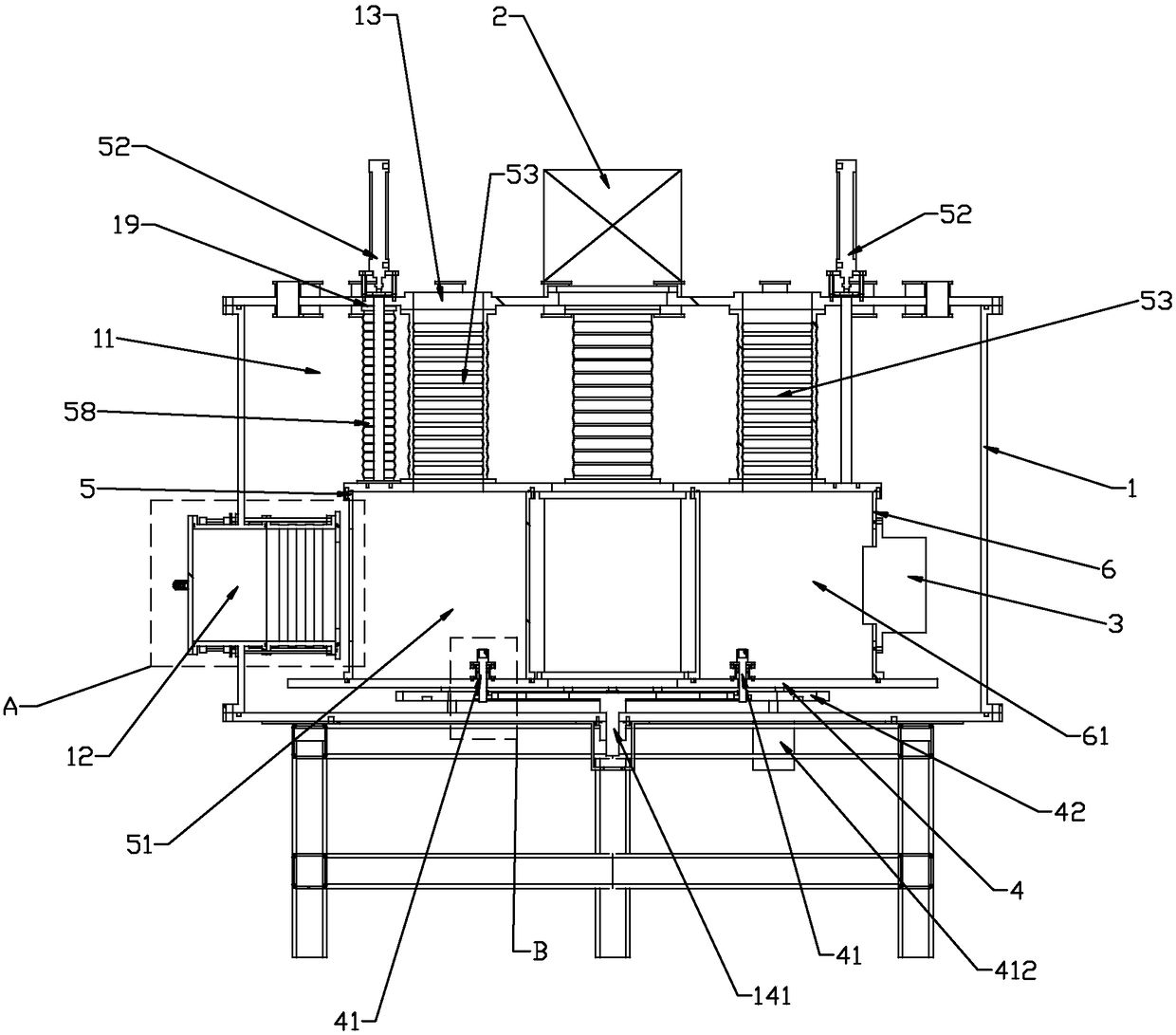
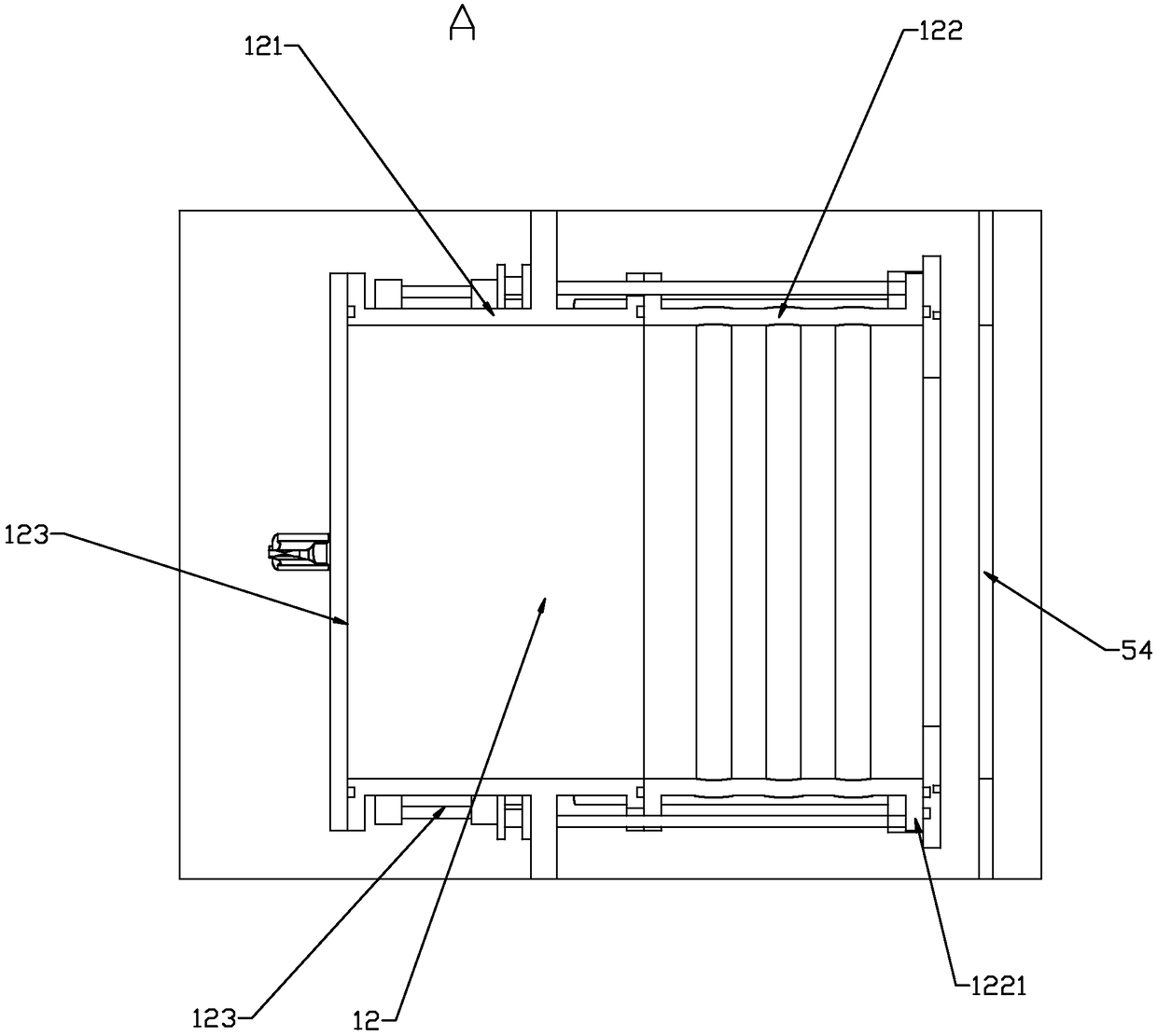
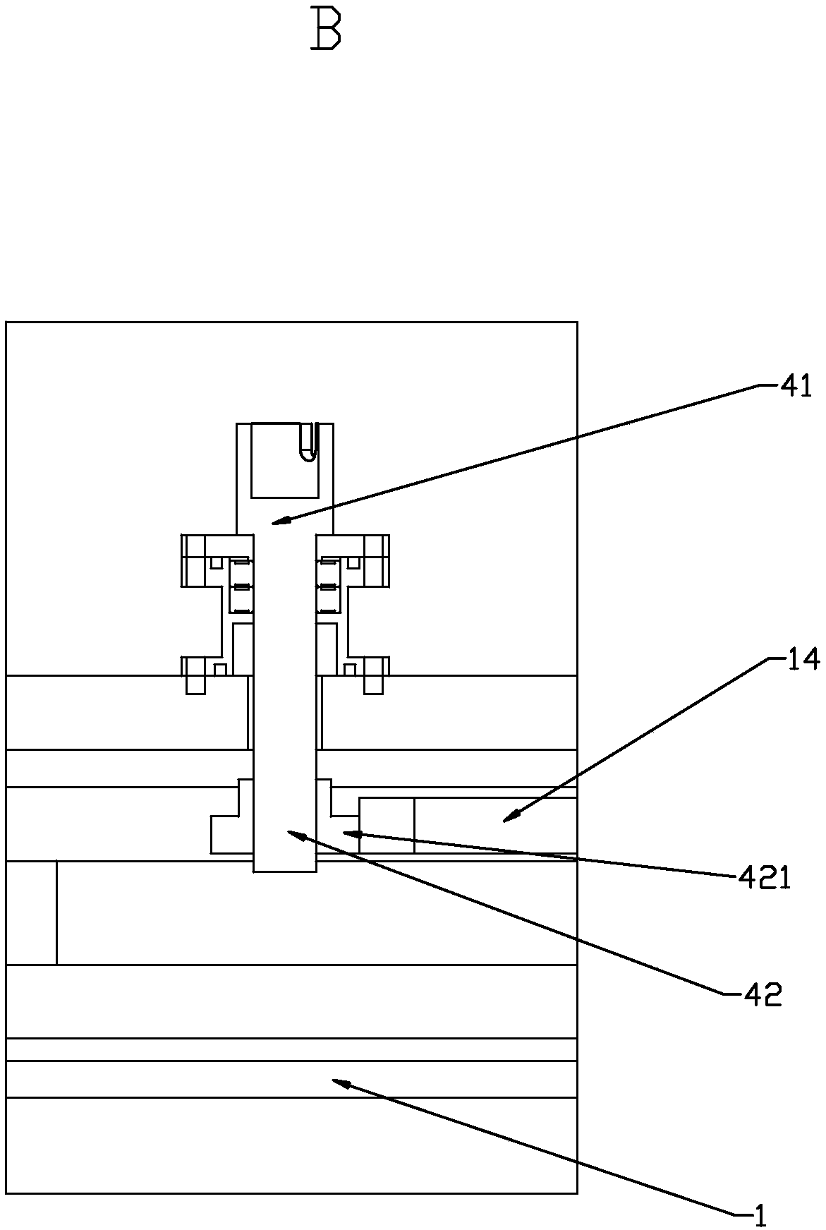
The invention relates to vertical circumferential circulation continuous type vapor deposition equipment. The equipment comprises a main chamber, a feeding chamber and a feeding port opening and closing system, process chambers and vapor deposition assemblies, a rotating frame system, a chamber lifting system, a vacuum system and vacuum pipelines; the vacuum system carries out the vacuum treatmenton the main chamber, the feeding chamber and the process chambers through the independent vacuum pipelines correspondingly, the feeding chamber and the process chambers are driven to ascend and descend through the pneumatic lifting mechanism, so that the feeding chamber and the process chambers are switched between the state in which the feeding chamber and the process chambers communicate with the main chamber and the state of the independent vacuum chamber, the vapor deposition assembly is laterally installed at each process chamber, and is connected to the outside of the vacuum chamber through a retractable corrugated pipe, so that different coating functions are realized; and the rotating frame system comprises a rotating disc and a double-rotating-disc rotating mechanism, a rotatingdisc rotating mechanism drives the rotating disc to carry out revolution or fixed-point self-rotating, the workpiece is transferred between the feeding chamber and the process chambers and undergoes fixed-point coating, so that circumferential rapid continuous vacuum coating is realized.

Description

technical field [0001] The invention belongs to the technical field of vapor deposition equipment, and in particular relates to a vertical circumferential circulation continuous vapor deposition equipment. Background technique [0002] Existing vapor deposition equipment can be divided into single-type coating machines and continuous coating equipment according to the number of vacuum chambers. [0003] The single-body coating machine usually consists of a vacuum chamber and an air extraction system. The vacuum coating process modules are loaded in different positions of the chamber. When the required vacuum degree is reached, the required vacuum coating process modules are activated in order to achieve The processing of the surface of the material, the single cavity leads to the need to open and close the door when the product is in and out, and the continuous production of the product cannot be carried out, which will greatly reduce the production efficiency and increase t...

Claims


Application Information

Patent Timeline
IPC IPC(8): C23C14/56C23C14/35C23C16/54
CPCC23C14/35C23C14/56C23C16/54
Inventor 郎文昌王向红刘伟
Owner WENZHOU POLYTECHNIC
Learn More