Self-provided power station boiler and cement kiln waste heat recovery coupling system

A waste heat recovery system and waste heat recovery technology, applied in the direction of furnaces, waste heat treatment, furnace components, etc., can solve the problems of low overall efficiency of waste heat power generation, low utilization rate of waste heat recovery, large power consumption, etc., and reduce the investment and construction of power transmission equipment , Improve operating efficiency and improve power generation efficiency

Pending Publication Date: 2018-07-13
成都建筑材料工业设计研究院有限公司
View PDF0 Cites 3 Cited by
  • Summary
  • Abstract
  • Description
  • Claims
  • Application Information

AI Technical Summary

Problems solved by technology

[0002] Because the cement production process itself needs to consume a lot of energy and there is a lot of energy waste in the cement production system, the cement production has become a well-known energy-consuming household, which requires a large amount of power consumption. In order to reduce energy consumption and solve power supply, conventional There are waste heat power generation projects in cement kiln construction. Since waste heat power generation projects usually use low parameters, the overall efficiency of waste heat power generation is only 18-20%, and the recovery and utilization rate of waste heat is very low. Some cement plants, especially some relatively backward countries in foreign countries, build self-provi

Method used


Image

  • Self-provided power station boiler and cement kiln waste heat recovery coupling system
  • Self-provided power station boiler and cement kiln waste heat recovery coupling system

Examples


Embodiment 1

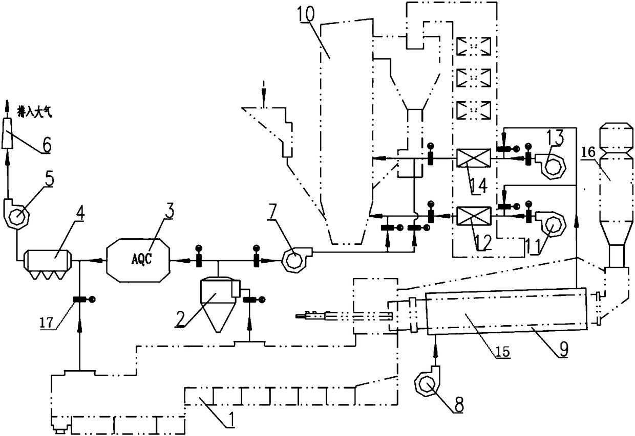
[0034] refer to figure 1 As shown, the self-provided power station circulating fluidized bed boiler and cement kiln waste heat recovery coupling system consists of kiln head waste heat recovery system, rotary kiln waste heat recovery system, and boiler system. The kiln head waste heat recovery system includes grate cooler 1 and dust collector 2 (first dedusting device), AQC boiler 3 (waste heat boiler), dust collector 4 (second dedusting device), induced draft fan 5 (induced air device), chimney 6, booster fan 7 (pressurized air device) and connecting pipes , the rotary kiln waste heat recovery system includes a blower 8 (air supply device), an air heating device 9 and connecting pipes, and the boiler system includes a circulating fluidized bed boiler 10, a primary fan 11, a primary air preheater 12, a secondary fan 13, Secondary air air preheater 14 and connecting pipes.

[0035] In the waste heat recovery system of the kiln head, air outlets are set in the middle and tail o...

Embodiment 2

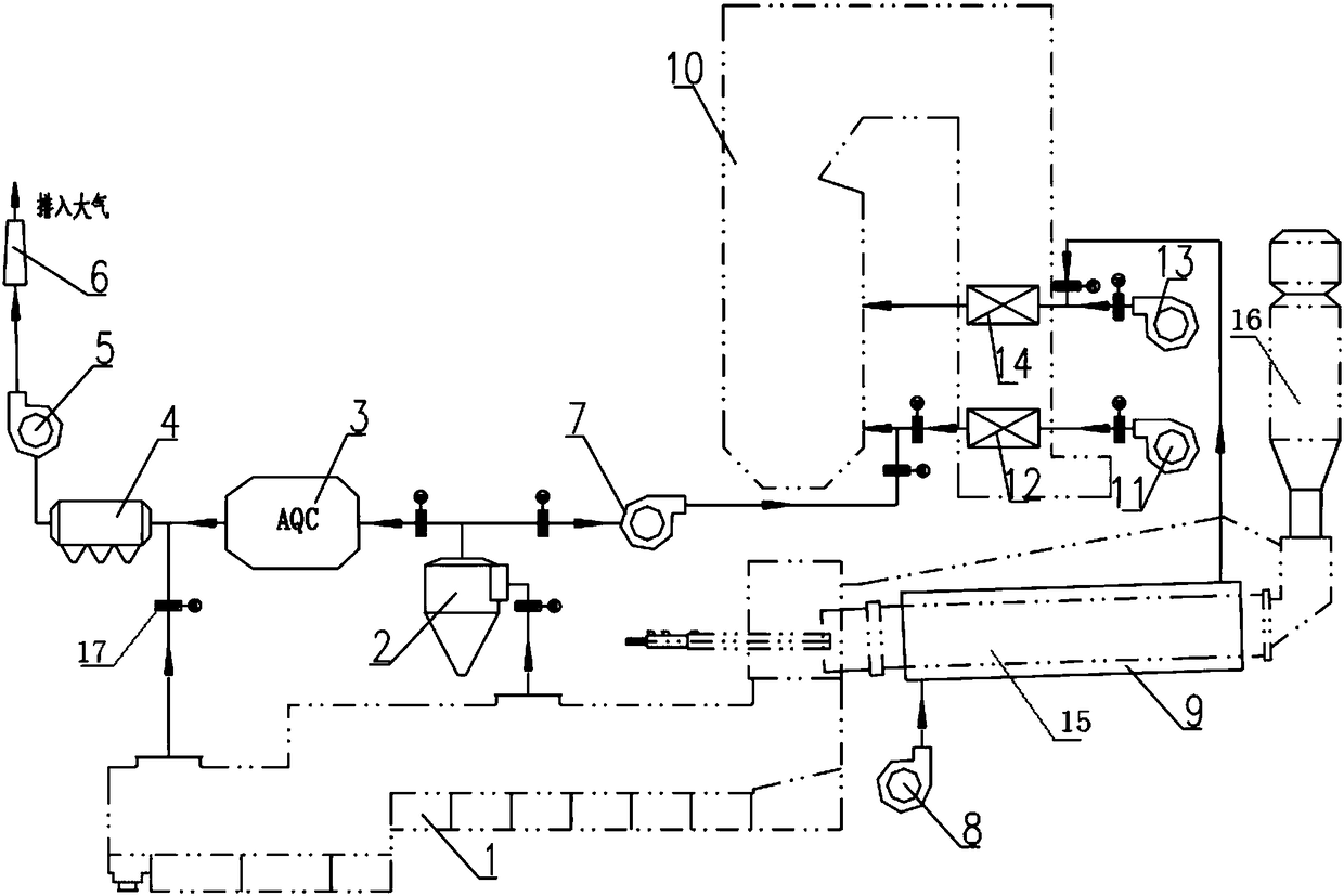
[0040] refer to figure 2 As shown, the self-provided power plant pulverized coal boiler and cement kiln waste heat recovery coupling system consists of kiln head waste heat recovery system, rotary kiln waste heat recovery system, and boiler system. The kiln head waste heat recovery system includes grate cooler 1, dust collector 2, AQC Boiler 3, dust collector 4, induced draft fan 5, chimney 6, booster fan 7 and connecting pipes, rotary kiln waste heat recovery system includes blower 8, air heating device 9 and connecting pipes, boiler system includes pulverized coal boiler 10, primary fan 11 , primary wind air preheater 12, secondary fan 13, secondary air air preheater 14 and connecting pipes.

[0041] In the waste heat recovery system of the kiln head, air outlets are set in the middle and tail of the grate cooler 1, and the hot air with a higher temperature extracted from the air outlet in the middle passes through the dust collector 2, and then passes through the AQC boile...


PUM


Abstract

The invention discloses a self-provided power station boiler and cement kiln waste heat recovery coupling system, and belongs to the technical field of cement production waste heat recovery and boilers. The self-provided power station boiler and cement kiln waste heat recovery coupling system comprises a kiln head waste heat recovery system, a rotary kiln waste heat recovery system and a power station boiler system; the kiln head waste heat recovery system comprises a grate cooler, a first dust removal device, a waste heat boiler, a second dust removal device, an induced draft device, a pressurizing air device and a connecting pipeline; the rotary kiln waste heat recovery system comprises an air supply device, an air heating device and a connecting pipeline; and the power station boiler system comprises a boiler, a primary air pipeline, a primary air preheater, a secondary air pipeline and a secondary air preheater. According to the self-provided power station boiler and cement kiln waste heat recovery coupling system, the overall power generation efficiency of a project for power generation can be effectively improved, the energy waste existing in the cement industry can be reduced, and the multiple purposes of effectively improving the overall power generation efficiency of the project for power generation, improving the operation efficiency of cement production and reducingthe operation energy consumption can be achieved.

Description

technical field [0001] The invention belongs to the field of cement production waste heat recovery and boiler technology, and in particular relates to a self-provided power plant boiler and cement kiln waste heat recovery coupling system. Background technique [0002] Because the cement production process itself needs to consume a lot of energy and there is a lot of energy waste in the cement production system, the cement production has become a well-known energy-consuming household, which requires a large amount of power consumption. In order to reduce energy consumption and solve power supply, conventional There are waste heat power generation projects in cement kiln construction. Since waste heat power generation projects usually use low parameters, the overall efficiency of waste heat power generation is only 18-20%, and the recovery and utilization rate of waste heat is very low. Some cement plants, especially some relatively backward countries in foreign countries, bui...

Claims


Application Information

Patent Timeline
IPC IPC(8): F27D17/00F23L15/00
CPCF23L15/00F27D17/002F27D17/004F27D17/008F27D2017/006Y02E20/34Y02P10/25
Inventor 王红伟余旭侯清琼郭敏万先浪于波刘建王国鸿
Owner 成都建筑材料工业设计研究院有限公司
Why Eureka
Try Eureka