Differential signal cable

A differential signal and cable technology, applied in the field of high-speed data transmission, can solve the problems of increasing the effective dielectric constant, increasing the diameter of high-speed digital signal transmission cables, etc., to achieve fast signal propagation, light weight, and good bending stability. Effect

Pending Publication Date: 2018-07-17
郑成
View PDF2 Cites 1 Cited by
  • Summary
  • Abstract
  • Description
  • Claims
  • Application Information

AI Technical Summary

Problems solved by technology

Such a structure increases the effective dielectric constant (PET dielectric constant 3.0 to 3.8) because polyethylene terephthalate (PET) acts as part of the insulating material, further increasing the diameter of the high-speed digital signal transmission cable

Method used


Image

  • Differential signal cable
  • Differential signal cable
  • Differential signal cable

Examples


Embodiment 1

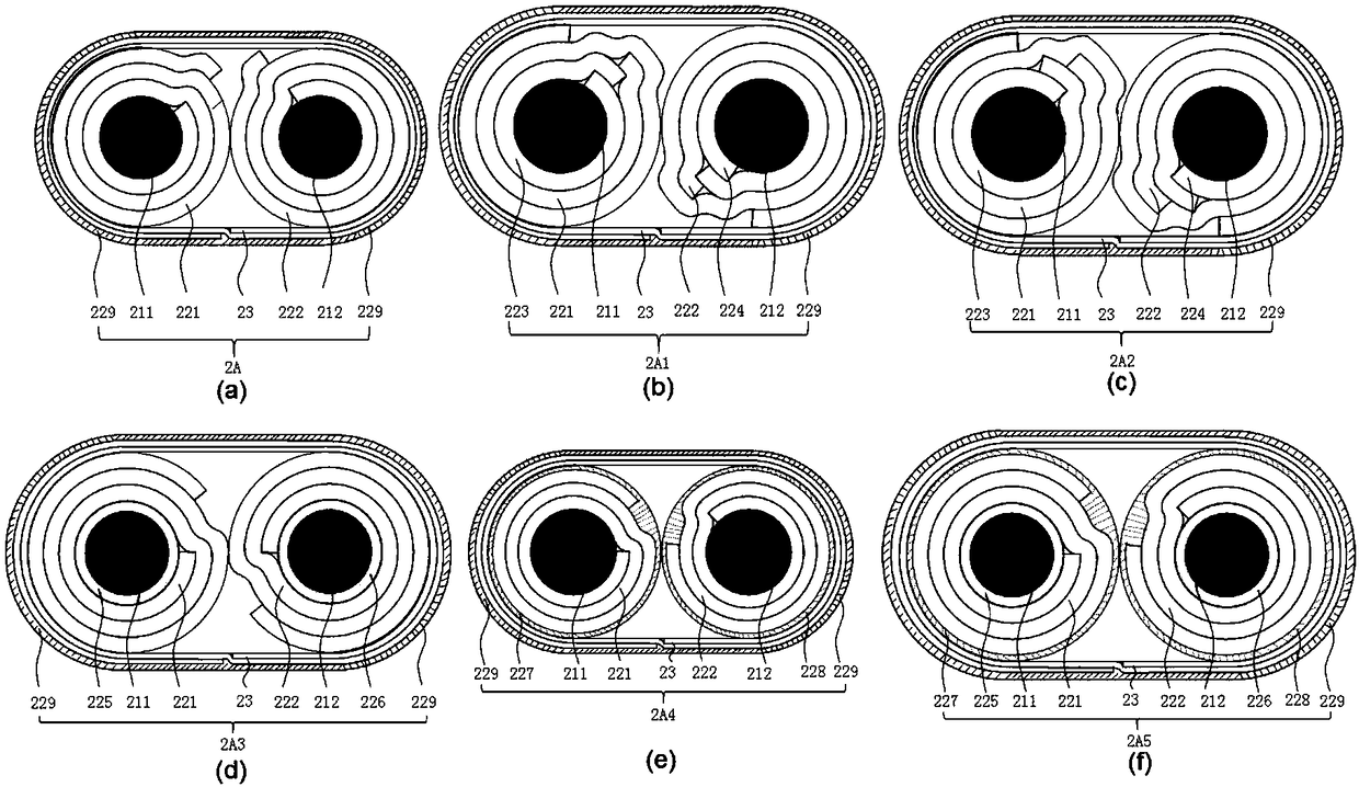
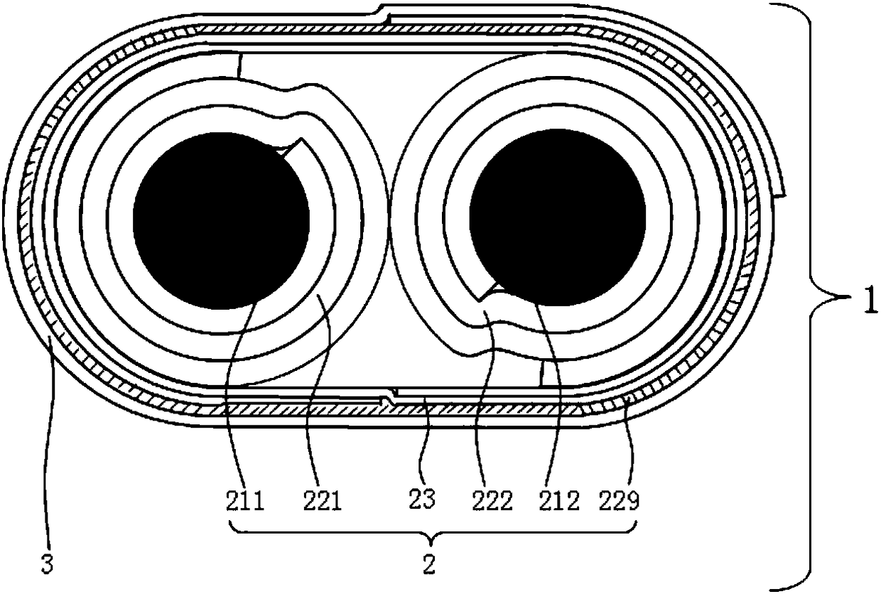
[0075] figure 2 It shows the cross-sectional structure diagram of Embodiment 1 of the differential signal cable of the present invention. Depend on figure 2 It can be seen that the differential signal cable 1 of the present invention is composed of an insulating core wire 2 and a shielding layer 3 . The insulated core wire 2 is composed of a pair of double conductors 211, 212 placed in parallel, first insulating dielectric tapes 221, 222 respectively wrapped on the double conductors 211, 212, and the first insulating dielectric tapes 221, 222 and the insulating stable layer 23 formed by co-wrapping the insulating stable layer 23 and the extruded third extruded insulating medium 229 covered outside the insulating stable layer 23. The insulation stabilization layer 23 tightly wraps the double conductors 211, 212 wrapped by the first insulating dielectric strips 221, 222 and the first insulating dielectric strips 221, 222 as a whole to enhance the fastening stability of the c...

Embodiment 2

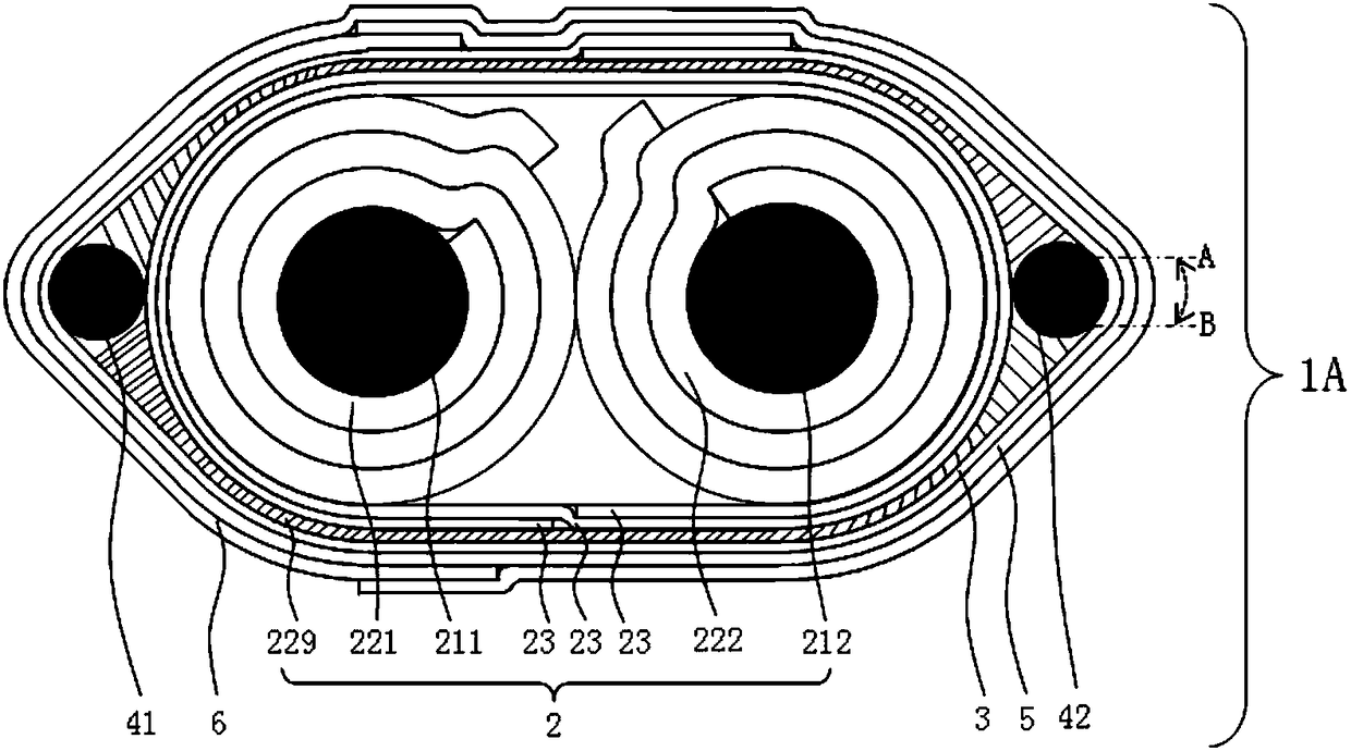
[0082] image 3 It shows the cross-sectional schematic diagram of Embodiment 2 of the differential signal cable of the present invention (the view perpendicular to the length direction of the conductor). Depend on image 3It can be seen that the differential signal cable 1A of the present invention is composed of an insulating core wire 2 , a shielding layer 3 , a first stable layer 5 , a second stable layer 6 and drain wires 41 and 42 . The insulated core wire 2 is composed of a pair of double conductors 211, 212 placed in parallel, first insulating dielectric tapes 221, 222 respectively wrapped on the double conductors 211, 212, and the first insulating dielectric tapes 221, 222 and the insulating stable layer 23 formed by co-wrapping the insulating stable layer 23 and the extruded third extruded insulating medium 229 covered outside the insulating stable layer 23. The insulation stabilization layer 23 tightly wraps the double conductors 211, 212 wrapped by the first insul...

Embodiment 3

[0092] Figure 4 Represents a schematic structural view of Embodiment 3 of the differential signal cable of the present invention, wherein Figure 4 (a) is a schematic structural diagram of a metal foil strip with a width difference between the two ends of the metal foil 31 and the carrier 32, Figure 4 (b) is a schematic diagram of the cross-sectional structure of the differential signal cable 1B (a view perpendicular to the length direction of the conductor). Depend on Figure 4 It can be seen that the differential signal cable 1B of the present invention is composed of an insulating core wire 2 , a shielding layer 3 , a first stable layer 5 , a second stable layer 6 and drain wires 41 and 42 . The insulated core wire 2 is composed of a pair of double conductors 211, 212 placed in parallel, first insulating dielectric tapes 221, 222 respectively wrapped on the double conductors 211, 212, and the first insulating dielectric tapes 221, 222 and the insulating stable layer 23...


PUM

PropertyMeasurementUnit
densityaaaaaaaaaa
dielectric lossaaaaaaaaaa

Abstract

A differential signal cable comprises an insulation core line and a shielding layer, wherein the insulation core line comprises a pair of dual conductors, first insulation medium tapes, an insulationstable layer and a third extrusion insulation medium, the pair of dual conductors are arranged in parallel, the first insulation medium tapes respectively wrap the dual conductors, the insulation stable layer jointly warps the first insulation medium tapes, the third extrusion insulation medium covers an outer surface of the insulation stable layer in an extruded manner, the materials of the firstinsulation medium tapes are tape-shaped materials with low density, low dielectric constant and low dielectric loss, and the first insulation medium tapes are integrally and tightly wrapped by the insulation stable layer. The differential signal cable has the characteristics of small external diameter, light weight, small bending radium, more flexibility, low elastic force and better cable electric characteristic consistency during mass production.

Description

technical field [0001] The invention relates to high-speed data transmission, in particular to a differential signal cable. Background technique [0002] With the development of IoT, LTE / LTE-A / 5G communication technology, the growth of personal computers, cloud storage, cloud computing, servers, and supercomputers, high-speed digital signals that can transmit data faster than ever before are required transmission cable. Optical fiber high-speed digital signal transmission cable provides the best data rate and performance for long-distance and high data rate transmission, because optical fiber high-speed digital signal transmission cable provides transmission with low attenuation and low bit error rate. However, due to expensive transceivers and power consumption of optical modules, passive copper cables capable of high-speed data transmission are still required for short distances. [0003] In products such as servers, routers, and storage devices that process high-speed d...

Claims


Application Information

Patent Timeline
Patent Type & Authority Applications(China)
IPC IPC(8): H01B7/02H01B7/04H01B7/18H01B11/06
CPCH01B7/0225H01B7/04H01B7/1805H01B11/06
Inventor 郑成
Owner 郑成
Why Eureka
Try Eureka