
Multi-filter core combined flue gas purifying processing device

A flue gas purification and treatment device technology, applied in gas treatment, dispersed particle filtration, air quality improvement, etc., can solve the problems of waste of energy, poor flue gas purification effect, short residence time, etc., to improve quality and safety, Easy to filter, easy to operate

Inactive Publication Date: 2018-07-24
张荷友
View PDF6 Cites 1 Cited by
  • Summary
  • Abstract
  • Description
  • Claims
  • Application Information

AI Technical Summary

Problems solved by technology

The gas-fired boiler flue gas contains about 18% water vapor (volume percentage), and there is a large amount of flue gas sensible heat and water vapor latent heat. polluted the environment
At present, a partition-type waste heat recovery heat exchanger (such as a finned tube economizer) is usually installed at the tail of the boiler, which can only recover part of the sensible heat in the flue gas, and the waste heat recovery efficiency is low, and the flow resistance of the flue gas is relatively large. Great back pressure on the boiler
[0003] In the prior art, a flue gas purification pool is used to absorb the soot in the flue gas through the water in the purification pool, and the heat in the flue gas is recycled by the pipeline. The residence time of the flue gas in the water is short, and the bubbles formed by the flue gas in the water Larger, which makes the flue gas purification effect poor, and the soot left after filtering in the flue gas purification pool also makes the water in the flue gas purification pool turbid, which also affects the separation effect of hot gas and soot, and the flue gas purification pool is long Time work will produce a lot of soot that needs to be cleaned up, and the amount of soot produced by different fuels is different. It is impossible to judge whether it needs to be cleaned from the time. It needs to be stopped for inspection, which is very inconvenient

Method used


Image

  • Multi-filter core combined flue gas purifying processing device
  • Multi-filter core combined flue gas purifying processing device
  • Multi-filter core combined flue gas purifying processing device

Examples


Embodiment Construction

[0021] The following will clearly and completely describe the technical solutions in the embodiments of the present invention with reference to the accompanying drawings in the embodiments of the present invention. Obviously, the described embodiments are only some, not all, embodiments of the present invention. Based on the embodiments of the present invention, all other embodiments obtained by persons of ordinary skill in the art without making creative efforts belong to the protection scope of the present invention.

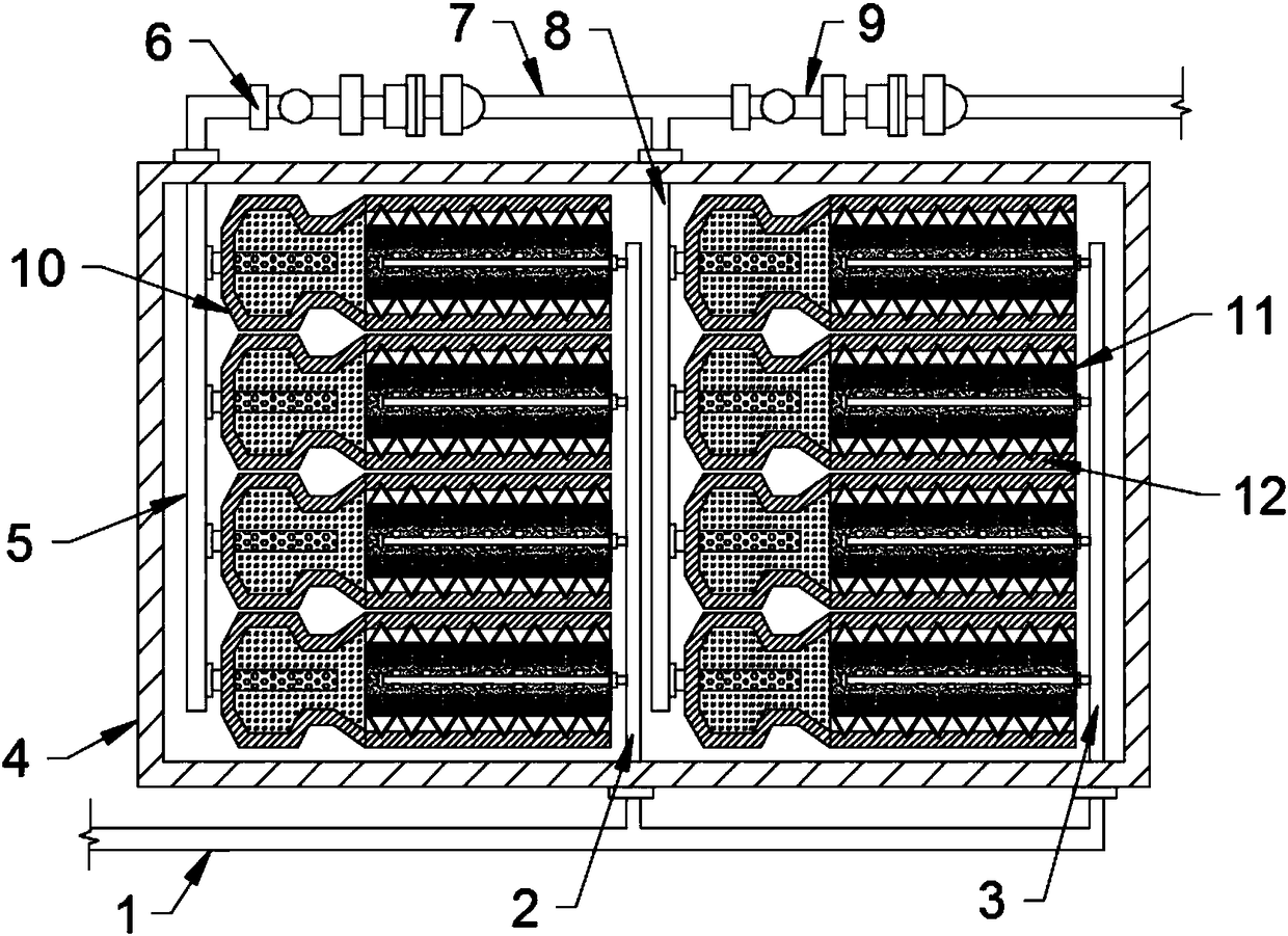
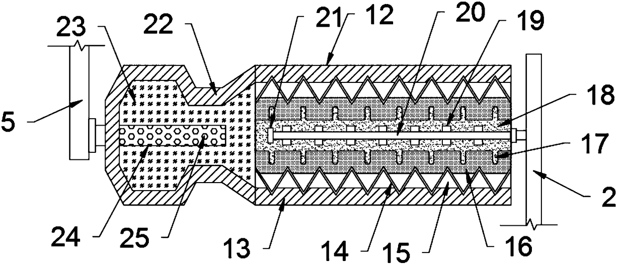
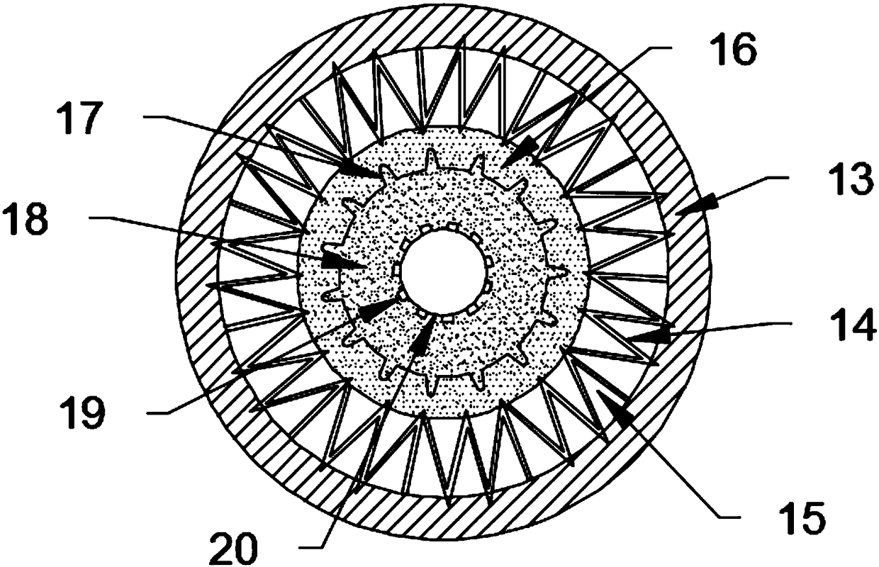
[0022] see Figure 1~3 , in an embodiment of the present invention, a multi-filter combination flue gas purification treatment device includes an air intake pipe 1, a purification box body 4, an exhaust pipe 7 and a purification filter element 12, and a purification component 1 is installed inside the purification box body 4. 10 and purification assembly two 11, purification assembly one 10 and purification assembly two 11 are all made up of a number of purifi...


PUM


Abstract

The invention discloses a multi-filter core combined flue gas purifying processing device. The multi-filter core combined flue gas purifying processing device comprises a gas inlet pipe, a purifying tank body, an exhaust pipe, and purifying filter cores; a purifying assembly 1 and a purifying assembly 2 are arranged in the purifying tank body; the purifying assembly 1 and the purifying assembly 2are composed of a plurality of successively arranged purifying filter cores; each purifying filter core is composed of a filter core housing, a support part, a gas exhaust channel, a filter cotton layer, an overflow groove, an adsorption filling material, a gas outlet nozzle, a gas guide tube, an end seal head, a gas collecting housing, a gas filtering layer, and an eduction tube; one end of eachfilter core housing is connected with the corresponding gas collecting housing; the multi-filter core combined flue gas purifying processing device is convenient for filtering treatment of flue gas, is capable of increasing purifying treatment efficiency, absorbing harmful substances such as sulfur dioxide, and dioxin in the air, is convenient for catalytic conversion of carbon monoxide and nitricoxide in flue gas into carbon dioxide and nitrogen dioxide for adsorption and purifying; flue gas is treated using the adsorption filling material, the filter cotton layers, and the gas filtering layers successively, and then is discharged, so that flue gas discharge quality and safety are improved, and environment pollution is avoided.

Description

technical field [0001] The invention relates to the field of smoke treatment equipment, in particular to a smoke purification treatment device combined with multiple filter elements. Background technique [0002] With the rapid development of my country's economy, the energy consumption is increasing day by day, and the air quality is also getting worse day by day. Today, as the requirements for energy conservation, emission reduction and environmental protection continue to increase, natural gas, as a clean energy source with high calorific value, continues to increase its proportion in my country's urban energy consumption structure. At present, most coal-fired boilers in large and medium-sized cities in my country have been changed to gas-fired boilers. For most gas-fired boilers, the exhaust gas temperature is still above 150°C, even as high as 250°C. The gas-fired boiler flue gas contains about 18% water vapor (volume percentage), and there is a large amount of flue g...

Claims


Application Information

Patent Timeline
IPC IPC(8): B01D53/86B01D46/30B01D53/56B01D53/62
CPCB01D46/30B01D53/04B01D53/8631B01D53/864B01D2257/2064B01D2257/302B01D2257/502Y02A50/20
Inventor 张荷友
Owner 张荷友
Learn More