Integrated waste heat boiler with steam temperature capable of being controlled and implementation method
A steam temperature and waste heat boiler technology, applied in the field of waste heat recovery boilers, can solve problems such as the large influence of waste heat power generation system stability and power generation efficiency, kiln head waste heat waste gas temperature, fluctuating waste gas flow, and large equipment footprint. Achieve the effect of reducing environmental pollution and energy waste, small footprint and compact equipment
- Summary
- Abstract
- Description
- Claims
- Application Information
AI Technical Summary
Problems solved by technology
Method used
Image

Examples
Embodiment Construction
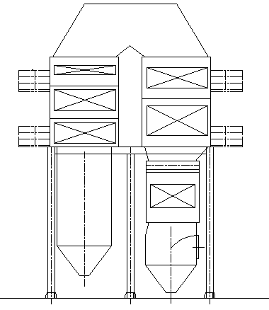
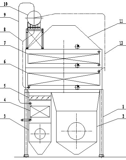
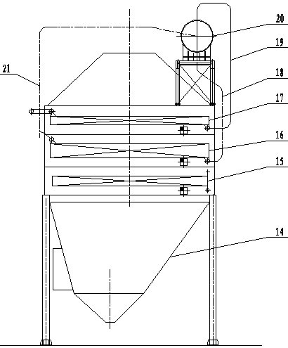
[0013] Further description will be made below in conjunction with the accompanying drawings.
[0014] Such as figure 1 , 2 , 3, 4, and 5, an integrated waste heat boiler capable of controlling steam temperature, including supporting steel frame 1, medium temperature settling chamber 2, high temperature settling chamber 3, modular sub-medium pressure superheater 4, flue gas flow control Valve 5, modular sub-medium pressure evaporator 6, modular sub-medium pressure economizer 7, sub-medium pressure boiler downpipe 8, sub-medium pressure boiler steam pipeline 9, sub-medium pressure boiler steam-water separator 10, steering smoke Road 11, sub-medium pressure boiler ascending pipe 12, platform escalator 13, flue gas outlet and ash hopper 14, hot water section 15, modular low-pressure evaporator 16, modular low-pressure superheater 17, low-pressure boiler descending pipe 18, low-pressure boiler Steam pipeline 19, low-pressure boiler steam-water separator 20, low-pressure boiler ri...
PUM
 Abstract
Description
Claims
Application Information
 - Generate Ideas
- Intellectual Property
- Life Sciences
- Materials
- Tech Scout
- Unparalleled Data Quality
- Higher Quality Content
- 60% Fewer Hallucinations
Browse by: Latest US Patents, China's latest patents, Technical Efficacy Thesaurus, Application Domain, Technology Topic, Popular Technical Reports.
© 2025 PatSnap. All rights reserved.Legal|Privacy policy|Modern Slavery Act Transparency Statement|Sitemap|About US| Contact US: help@patsnap.com