


Quick Research
Generate reliable direction feasibility study reports for your R&D in just a few steps.

Technical Q&A
Discover and master advanced knowledge NOW. Basics, ideas, possibilities, all at once.

Find Solutions
As an expert in R&D theories, this can generate solutions to your technical problems instantly.

Evaluate Feasibility
Analyze your overall solution with one click, know your potential R&D risks in advance.

Monitor Landscape
Get weekly tech updates, stay abreast of the latest tech innovations and key insights.
Plasma etching and deposition equipment and method
A technology of plasma and deposition equipment, applied in discharge tubes, electrical components, circuits, etc., can solve the problem of waste liquid polluting the environment, etc., and achieve good results, controllable etching or deposition process, uniform film quality and no pinholes Effect
- Summary
- Abstract
- Description
- Claims
- Application Information
AI Technical Summary
Problems solved by technology
Method used
Image

Examples
Embodiment 1
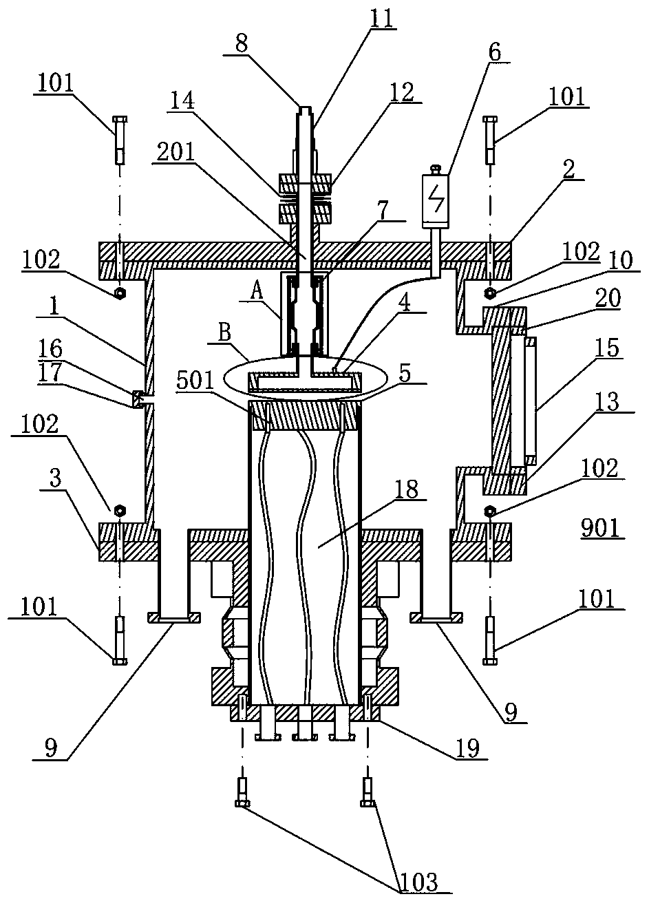
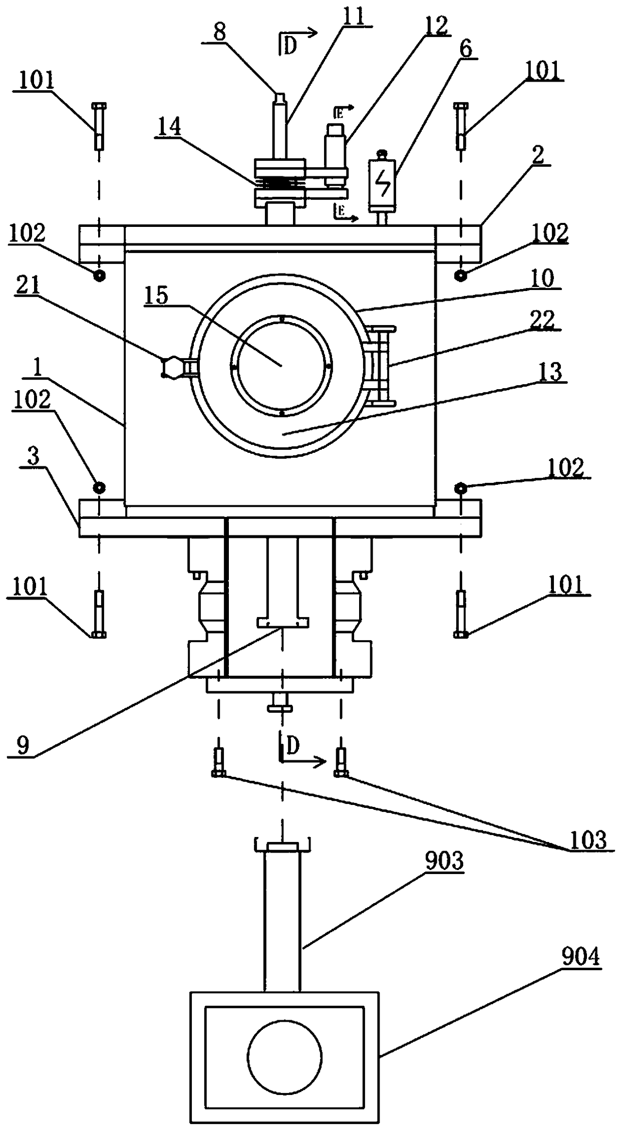
[0047] like Figure 1 to Figure 8 As shown, a plasma etching and deposition equipment includes a reaction chamber 1, an upper body 2, a lower body 3, an upper electrode, and a lower electrode 18;
[0048]The upper electrode includes an air inlet 8, a long rod 11, a ceramic rod 702, a ceramic protective cover 7, and an upper electrode plate 4. The air inlet 8 is provided at one end of the long rod 11 and one end of the ceramic rod 702. The ceramic rod fixing bolt 703 is connected to the end of the long rod 11 away from the air inlet 8, and the other end of the ceramic rod 702 is connected to the upper pole plate 4 by the ceramic rod fixing bolt 703. The ceramic protective cover 7 is arranged outside the ceramic rod 702, and is connected to the long rod 11 and the upper pole plate 4 through the ceramic protective cover fixing bolts 701;
[0049] The long rod 11 is hollow inside, the ceramic rod 702 is hollow inside, and the upper pole plate 4 is hollow inside, and the long rod ...
Embodiment 2
[0064] A plasma etching method is carried out according to the following steps:
[0065] Step A: heating the lower electrode plate through the thermocouple 501 arranged in the lower electrode plate 5, and the heating temperature is 110°C;
[0066] Step B: Put the material to be plasma-etched into the lower plate 5 of the reaction chamber through the sealing door 13;
[0067] Step C: adjust the distance between the upper and lower pole plates to 29mm through the height adjustment device 12;
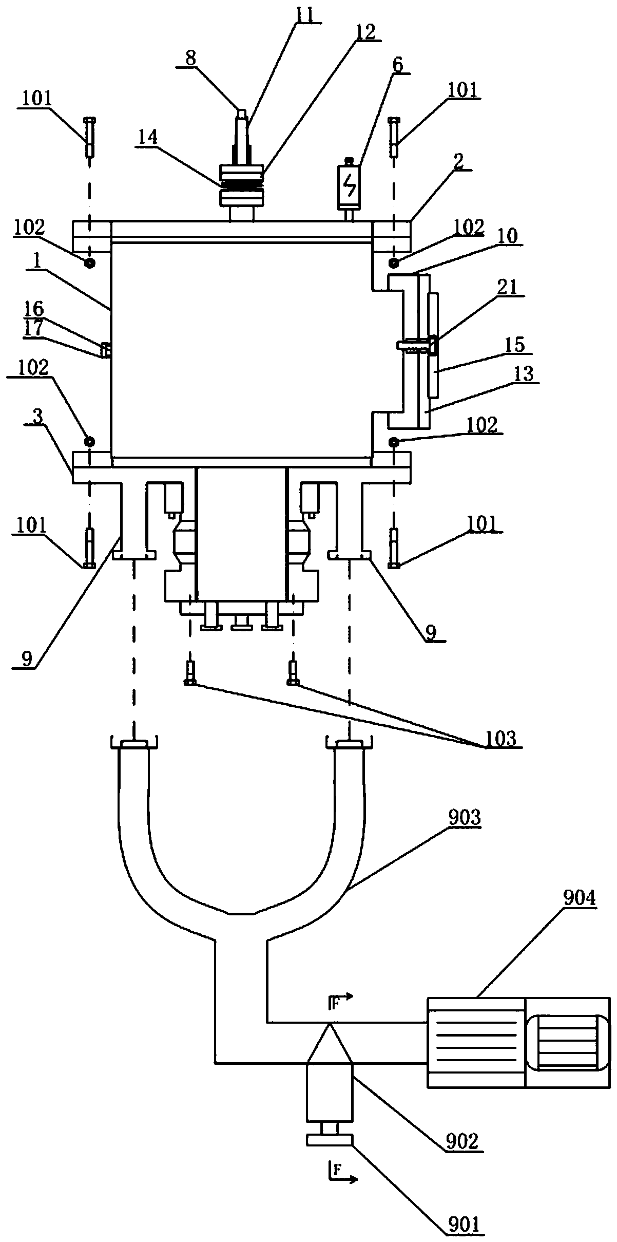
[0068] Step D: After closing the sealing door 13, turn on the vacuum pump 904 to evacuate, so that the vacuum degree in the reaction chamber 1 is less than 1.3Pa;
[0069] Step E: pass the reaction gas into the reaction chamber 1 through the air inlet 8;
[0070] Step F: stabilize the gas pressure in the reaction chamber 1 at 65 Pa by adjusting the pumping rate adjustment knob 901;
[0071] Step G: start the radio frequency power supply 6 to discharge, and the discharge power is 120W; ...
Embodiment 3
[0074] A plasma deposition method is carried out according to the following steps:
[0075] Step A: heating the lower electrode plate through the thermocouple 501 arranged in the lower electrode plate 5, and the heating temperature is 110°C;
[0076] Step B: Put the material to be modified by plasma deposition into the lower plate 5 of the reaction chamber through the sealing door 13;
[0077] Step C: adjust the distance between the upper and lower pole plates to 29mm through the height adjustment device 12;
[0078] Step D: After closing the sealing door 13, turn on the vacuum pump 904 to evacuate, so that the vacuum degree in the reaction chamber 1 is less than 1.3Pa;
[0079] Step E: pass the reaction gas into the reaction chamber 1 through the air inlet 8;
[0080] Step F: stabilize the gas pressure in the reaction chamber 1 at 130 Pa by adjusting the pumping rate adjustment knob 901;
[0081] Step G: start the radio frequency power supply 6 to discharge, and the discha...
PUM
 Abstract
Description
Claims
Application Information
 - R&D Engineer
- R&D Manager
- IP Professional
- Industry Leading Data Capabilities
- Powerful AI technology
- Patent DNA Extraction
Browse by: Latest US Patents, China's latest patents, Technical Efficacy Thesaurus, Application Domain, Technology Topic, Popular Technical Reports.
© 2024 PatSnap. All rights reserved.Legal|Privacy policy|Modern Slavery Act Transparency Statement|Sitemap|About US| Contact US: help@patsnap.com