Punching device for motorcycle frame

A drilling device and motorcycle technology, applied in the direction of positioning device, boring/drilling, drilling/drilling equipment, etc., can solve the problems of low degree of automation, lack of fixing mechanism, lower drilling efficiency, etc., and achieve improved Efficiency, the effect of improving the efficiency of punching

Inactive Publication Date: 2018-08-03
重庆荣爵科技有限公司
View PDF4 Cites 7 Cited by
  • Summary
  • Abstract
  • Description
  • Claims
  • Application Information

AI Technical Summary

Problems solved by technology

[0004] Although the above-mentioned patented scheme overcomes the shortcomings of the traditional punching method, there are still some points to be improved in the scheme: 1. The device lacks a fixing mechanism. When punching a hole, a person needs to hold a steel pipe to fix it, and the distance between the human hand and the device Closer, there are potential safety hazards, and manual feeding makes the degree of automation lower and the drilling efficiency relatively lower; 2. The device lacks a waste recycling mechanism, and the waste generated after each stamping head completes stamping will remain in the In the mold seat, in order to avoid affecting the next drilling, manual cleaning is required, which reduces the overall drilling efficiency

Method used


Image

  • Punching device for motorcycle frame
  • Punching device for motorcycle frame
  • Punching device for motorcycle frame

Examples


Embodiment Construction

[0019] The present invention will be described in further detail below by means of specific embodiments:

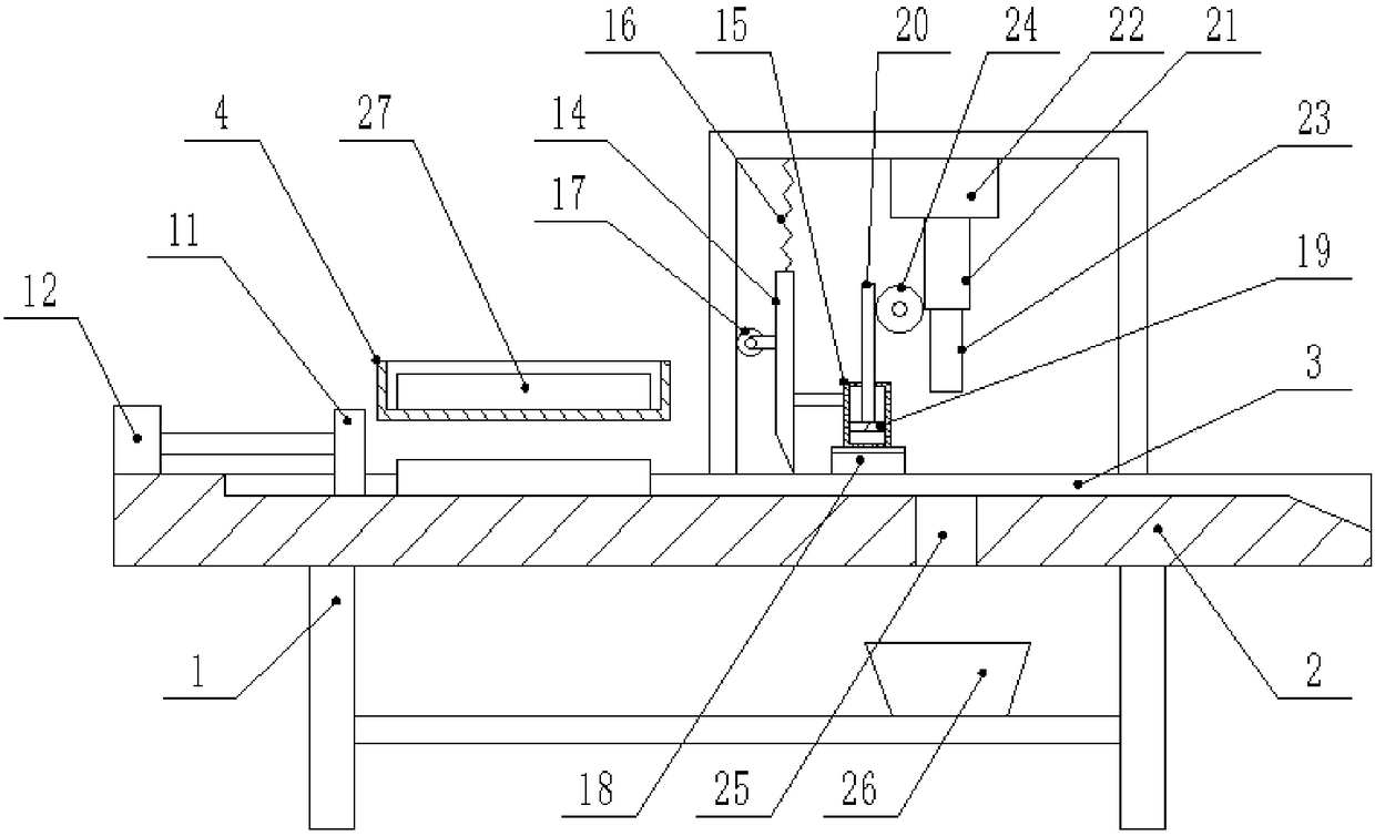
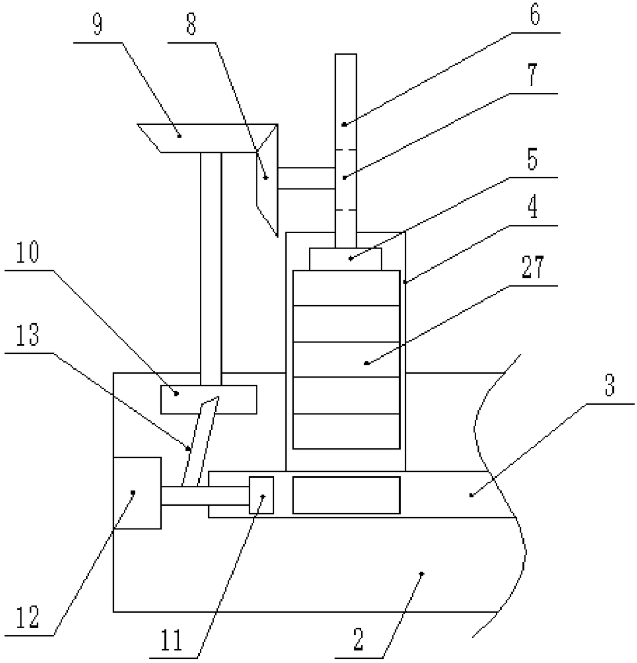
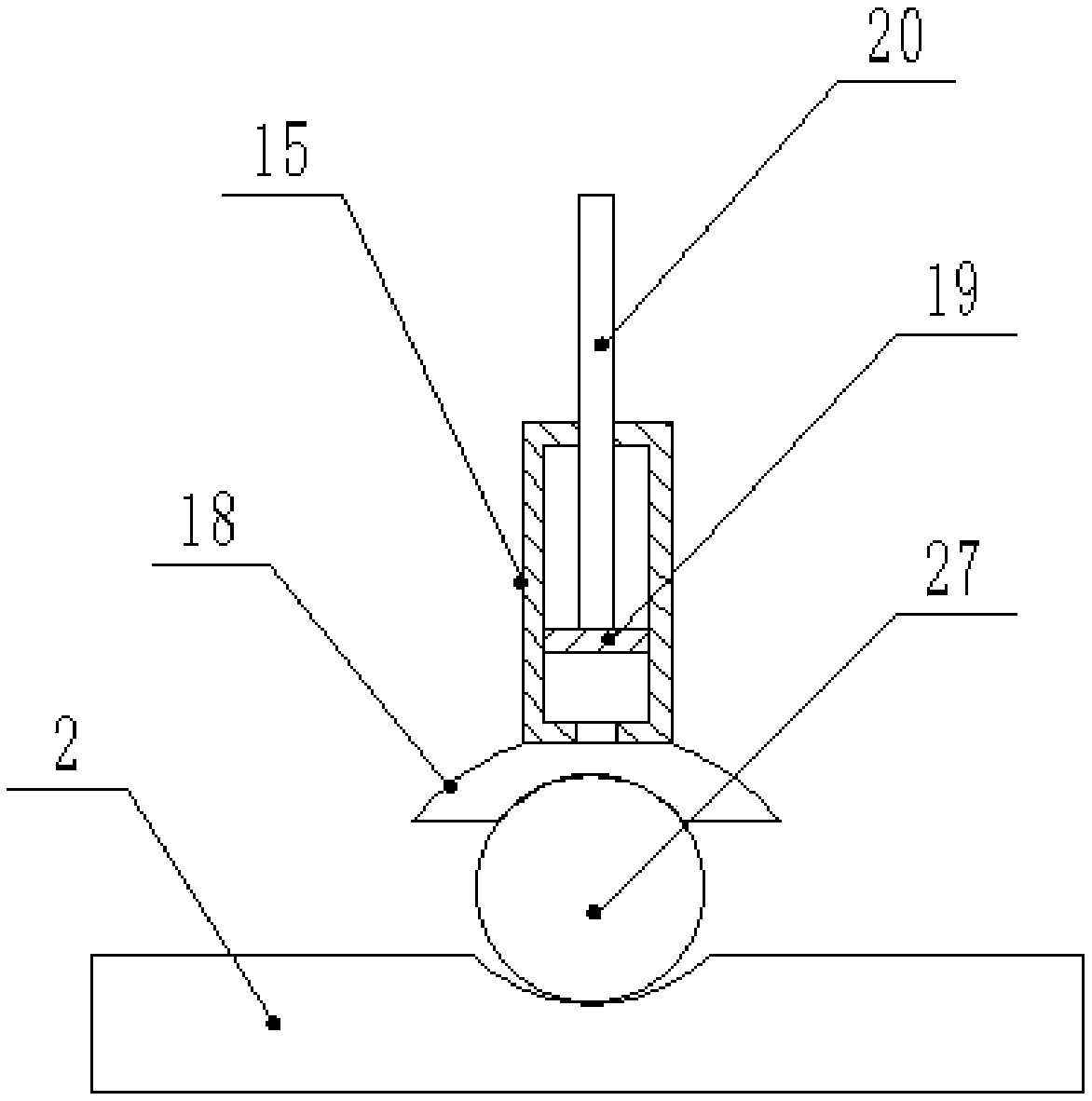
[0020] The reference signs in the drawings of the description include: frame 1, workbench 2, material guide trough 3, transmission trough 4, push plate 5, rack 6, second gear 7, first bevel gear 8, second bevel gear 9. Ratchet 10, push block 11, first cylinder 12, pawl 13, wedge rod 14, piston cylinder 15, spring 16, guide wheel 17, suction cup 18, piston 19, piston rod 20, base 21, second cylinder 22, drill bit 23, first gear 24, waste guide hole 25, waste recovery barrel 26, steel pipe 27.

[0021] This embodiment is basically as attached Figure 1 to Figure 3 Shown:

[0022] The motorcycle frame punching device includes a frame 1, on which a workbench 2 is fixed by bolts, on which a guide groove 3 is opened, and the right side of the guide groove 3 is a downwardly inclined outlet. The table 2 is provided with a feeding mechanism, a fixing mechanism and a punching me...


PUM


Abstract

The invention relates to the technical field of frame machining, and discloses a punching device for a motorcycle frame. The punching device comprises a machine frame, a workbench is fixed to the machine frame, and a guide chute is formed in the workbench. The workbench is sequentially provided with a feeding mechanism, a fixing mechanism and a punching mechanism which are arranged along the guidechute. The feeding mechanism comprises a conveying trough, a discharging outlet of the conveying trough is in butt joint with the guide chute; and a push plate is slidably connected into the conveying trough, and a pushing block is slidably connected into the guide chute. The fixing mechanism comprises a wedge rod and a piston cylinder which are slidably connected to the machine frame, and the piston cylinder is fixedly connected with the wedge rod. A suction cup communicating with the piston cylinder, a piston is slidably connected into the piston cylinder, and a piston rod is fixed to the piston. The punching mechanism comprises a base, and a drill bit is fixed to the base. The base and the piston rod are separately provided with gear teeth, and a first gear is rotatably connected to the machine frame. One side of the first gear meshes with the piston rod, and the other side of the first gear meshes with the base. The punching device for the motorcycle frame can automatically feed,and can fix a steel pipe when punching, and simultaneously perform the automatic punching.

Description

technical field [0001] The invention relates to the technical field of vehicle frame processing, in particular to a motorcycle frame punching device. Background technique [0002] Motorcycle frames are usually assembled from steel pipes, and the steel pipes need to be perforated during assembly to facilitate better connections between the steel pipes. The traditional punching method is manual punching with a hand-held punch. This method is not only labor-intensive and inefficient, but also cannot guarantee the quality of the hole, which may easily lead to poor pass rate. [0003] In order to solve the above-mentioned problems, there is a punching device in the prior art, which includes a frame on which a mold seat is fixed, a stamping head is slidably connected to the frame above the mold seat, and a punching head for driving the stamping head is fixed on the frame. the drive mechanism. When punching, extend the steel pipe into the mold seat, align the part of the steel pi...

Claims


Application Information

Patent Timeline
Patent Type & Authority Applications(China)
IPC IPC(8): B23B41/00B23B47/34B23Q7/00B23Q3/08
CPCB23B41/00B23B47/34B23Q3/064B23Q3/088B23Q7/00
Inventor 杨雨涵
Owner 重庆荣爵科技有限公司
Why Eureka
Try Eureka