Method for definitively polishing Wolter-I type optical mandrel
A deterministic, mandrel technology, applied in the field of deterministic polishing of Wolter-I optical mandrels with elastic spherical polishing tools, can solve the problems of inconvenient integration, instability of airbags, expensive ultra-precision deterministic polishing equipment, etc. The effect of improving machining accuracy and machining efficiency
- Summary
- Abstract
- Description
- Claims
- Application Information
AI Technical Summary
Problems solved by technology
Method used
Image

Examples
Embodiment Construction
[0037]The technical solution of the present invention will be further described below in conjunction with the accompanying drawings, but it is not limited thereto. Any modification or equivalent replacement of the technical solution of the present invention without departing from the spirit and scope of the technical solution of the present invention should be covered by the present invention. within the scope of protection.
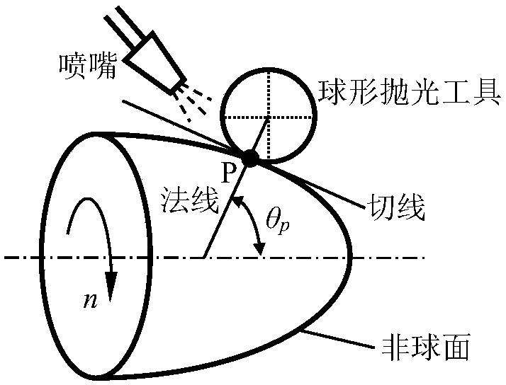
[0038] The invention provides a method for deterministically polishing a Wolter-I optical mandrel. The so-called deterministic polishing refers to the flexible control of polishing tools and workpieces through computer technology to realize the relative position and pressure between the tool and the workpiece. , speed, polishing time and other parameters deterministic control. The specific details are as follows:
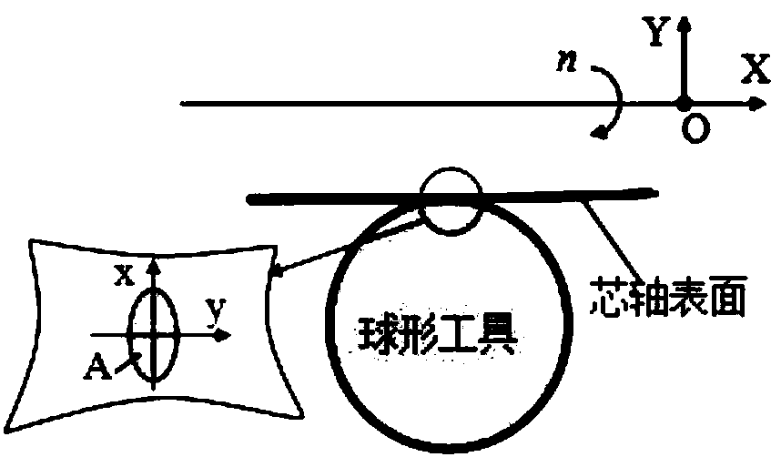
[0039] 1. Polishing method:
[0040] Polishing tools are spherical elastomers that can easily change shape to fit the aspheric surfaces tha...
PUM
 Abstract
Description
Claims
Application Information