Multispectral photoacoustic and optical coherence tomography dual-mode imaging device and multispectral photoacoustic and optical coherence tomography dual-mode imaging method

A technology of optical coherence tomography and dual-modal imaging, which is applied in the direction of material analysis, measuring device, color/spectral characteristic measurement through optical means, and can solve the problem of increasing debugging complexity and imaging time, and limiting the clinical development of complementary imaging and other problems to achieve the effect of solving inconvenient

Active Publication Date: 2018-08-07
SOUTH CHINA NORMAL UNIVERSITY
View PDF9 Cites 8 Cited by
  • Summary
  • Abstract
  • Description
  • Claims
  • Application Information

AI Technical Summary

Problems solved by technology

Frequency-domain OCT uses a wide-band light source in the near-infrared band, while multispectral photoacoustic imaging generally requires multiple lasers or OPO lasers to achieve multi-wavelength excitation. D

Method used


Image

  • Multispectral photoacoustic and optical coherence tomography dual-mode imaging device and multispectral photoacoustic and optical coherence tomography dual-mode imaging method
  • Multispectral photoacoustic and optical coherence tomography dual-mode imaging device and multispectral photoacoustic and optical coherence tomography dual-mode imaging method
  • Multispectral photoacoustic and optical coherence tomography dual-mode imaging device and multispectral photoacoustic and optical coherence tomography dual-mode imaging method

Examples


Embodiment 1

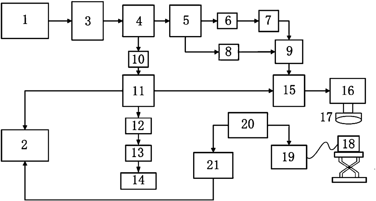
[0038] Such as figure 1 As shown, this embodiment provides a multi-spectral photoacoustic and optical coherence tomography dual-mode imaging device, which includes a multi-spectral photoacoustic / optical coherence tomography excitation light source 1, a dichroic mirror assembly, and a scanning head components, a photoacoustic signal detection component 2, an interference signal detection component, and a signal acquisition / processing component.

[0039] The excitation light source 1 is produced by a supercontinuum laser and connected to the filter 3. The wavelength range of the supercontinuum laser is 400-2400nm. The filter 3 is adjustable, and the required output wavelength range can be selected. Adjusting the filter 3 can obtain laser light in the wavelength range of 500nm-820nm.

[0040] The dichroic mirror assembly includes a first dichroic mirror 4 , a second dichroic mirror 5 , a third dichroic mirror 9 , a beam splitter 11 , a reflection mirror 14 and a fourth dichroic mi...

Embodiment 2

[0054] This embodiment provides a multi-spectral photoacoustic and optical coherence tomography dual-modal imaging method, which is implemented based on the device in the above-mentioned embodiment 1, and includes the following steps:

[0055] S1. Place the sample on the one-dimensional lifting table, place the sample directly below the scanning head assembly, and place the photoacoustic signal detection assembly directly below the sample;

[0056] S2. The photoacoustic excitation light (narrowband light source) for multispectral photoacoustic imaging and the broadband light source for optical coherence tomography are combined into one by the fourth dichroic mirror in the dichroic mirror assembly. The head assembly illuminates the sample;

[0057] In this step, the photoacoustic excitation light used for multispectral photoacoustic imaging is a dual-wavelength photoacoustic excitation light, and a narrow range of light waves can be selected for the excitation light source thro...

Embodiment 3

[0065] This embodiment is a specific application example, which provides a multi-spectral photoacoustic and optical coherence tomography dual-modal imaging method, including the following steps:

[0066] 1) Obtain experimental materials: inject red ink and blue ink into glass tubes with an inner diameter of 300um and an outer diameter of 500um to simulate blood vessels, and the wall of the tube is 200um to simulate tissue structure, and fix the glass tubes on the agar surface.

[0067] 2) Put the glass tube on the ultrasonic transducer, and coat a layer of ultrasonic coupling agent between the agar and the ultrasonic transducer, and then place the ultrasonic transducer on the one-dimensional lifting platform.

[0068]3) The broadband light source for optical coherence tomography and the narrowband light source for multispectral photoacoustic imaging are combined into one through a dichroic mirror, focused by an X-Y two-dimensional scanning galvanometer and a lens, and a one-dim...


PUM


Abstract

The invention discloses a multispectral photoacoustic and optical coherence tomography dual-mode imaging device and a multispectral photoacoustic and optical coherence tomography dual-mode imaging method. The multispectral photoacoustic and optical coherence tomography dual-mode imaging device comprises a multispectral photoacoustic/optical coherence tomography excitation light source, a dichroscope assembly, a scanning head assembly, a photoacoustic signal detection assembly, an interference signal detection assembly and a signal acquisition/processing assembly. The photoacoustic signal detection assembly and the interference signal detection assembly are connected with the signal acquisition/processing assembly, the scanning head assembly is positioned right above samples and is connected with the signal acquisition/processing assembly, the photoacoustic signal detection assembly is positioned below the samples, the dichroscope assembly is connected with the interference signal detection assembly and the scanning head assembly, and the excitation light source is generated by a super-continuous spectrum laser device and is connected with the dichroscope assembly by an adjustable filter. The multispectral photoacoustic and optical coherence tomography dual-mode imaging device and the multispectral photoacoustic and optical coherence tomography dual-mode imaging method have theadvantages that a dual-mode complementary imaging system can be built by the aid of the multispectral photoacoustic and optical coherence tomography dual-mode imaging device and the multispectral photoacoustic and optical coherence tomography dual-mode imaging method, and accordingly clinical development of complementary imaging can be promoted to a certain extent.

Description

technical field [0001] The invention relates to a dual-mode imaging device and method, in particular to a multi-spectral photoacoustic and optical coherence tomography dual-mode imaging device and method, belonging to the technical field of photoacoustic imaging. Background technique [0002] When the pulsed laser irradiates the organism, the absorber in the biological tissue absorbs the light energy, causing the local rapid temperature rise of the organism, and the volume of the organism expands due to heat. Expansion and contraction, thereby causing mechanical vibration of the tissue, and spreading from the inside out to generate pressure waves, this is the principle of ultrasonic waves generated by light, that is, the photoacoustic effect. Therefore, the photoacoustic imaging technology based on the photoacoustic effect came into being and gradually developed. The photoacoustic signal is received by an ultrasonic detector, amplified, converted, and collected to realize i...

Claims


Application Information

Patent Timeline
IPC IPC(8): G01N21/17G01N21/45G01N21/39
CPCG01N21/1702G01N21/39G01N21/45G01N2021/1772
Inventor 陈重江常影杨思华邢达
Owner SOUTH CHINA NORMAL UNIVERSITY
Why Eureka
Try Eureka