Check patentability & draft patents in minutes with Patsnap Eureka AI!

Composite SCR denitration catalyst and preparation method thereof

A technology of denitration catalyst and denitration rate, which is applied in the field of composite SCR denitration catalyst and its preparation, can solve the problem that catalysts and low temperature catalysts cannot adapt to temperature fluctuations, etc., and achieve the effects of reducing software investment costs and equipment investment costs.

Active Publication Date: 2018-08-17
江苏浩日朗环保科技有限公司
View PDF4 Cites 3 Cited by
  • Summary
  • Abstract
  • Description
  • Claims
  • Application Information

AI Technical Summary

Problems solved by technology

[0007] The purpose of the present invention is to provide a composite SCR denitrification catalyst and its preparation method, which solves the problem that existing conventional catalysts and low-temperature catalysts cannot adapt to large temperature fluctuations

Method used


Image

  • Composite SCR denitration catalyst and preparation method thereof
  • Composite SCR denitration catalyst and preparation method thereof
  • Composite SCR denitration catalyst and preparation method thereof

Examples


preparation example Construction

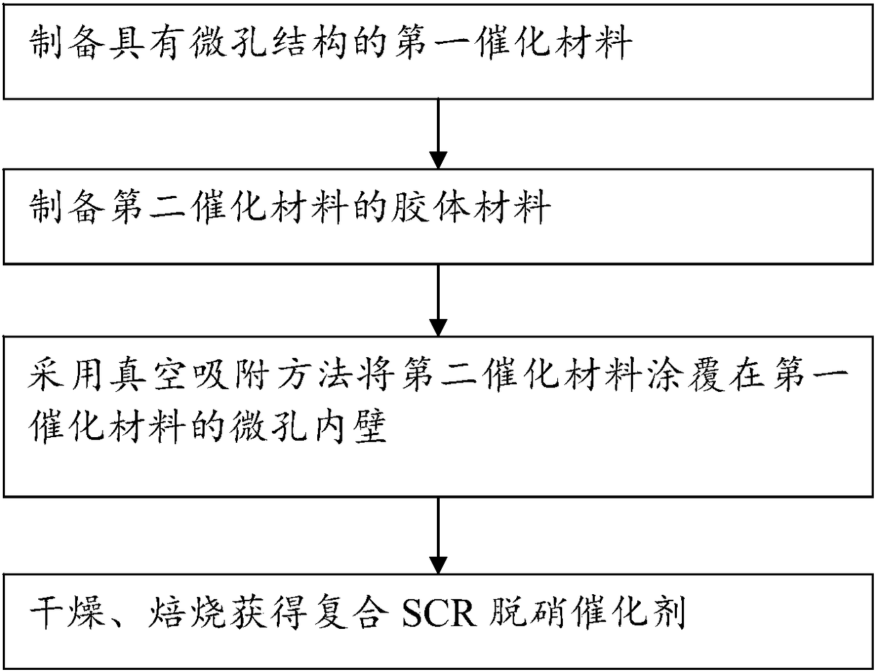
[0041] combine figure 1 As shown, the embodiment of the present application also discloses a preparation method of a composite SCR denitration catalyst, including:

[0042] (1), preparing the first catalytic material with a microporous structure; wherein the calcination temperature is 500-650°C, and the time is 20-35h,

[0043] (2), preparing the colloidal material of the second catalytic material;

[0044] (3), adopting the vacuum adsorption method to coat the second catalytic material on the micropore inner wall of the first catalytic material;

[0045] (4) drying and roasting to obtain a composite SCR denitration catalyst.

[0046] In a preferred embodiment, in step (4), the drying condition is 80-120° C., and the drying time is 1-5 hours.

[0047] In a preferred embodiment, in step (4), the calcination condition is 400-500°C, and the calcination time is 3-8 hours.

[0048] Due to the composite preparation of conventional temperature catalysts and low temperature coatin...

Embodiment 1

[0051] (1) Preparation of the first catalytic material (conventional temperature catalyst, optimal denitrification temperature 300-420°C)

[0052] The preparation of conventional temperature catalysts is realized by means of compounding, extrusion molding, drying and roasting.

[0053] Among them, the raw materials include:

[0054] 60 parts of titanium dioxide;

[0055] 0.5 parts of ammonium metavanadate;

[0056] 3 parts of ammonium metatungstate;

[0057] 6 parts glass fiber;

[0058] 2 parts wood pulp

[0059] 1.5 parts of binder;

[0060] 3 parts of silicon dioxide;

[0061] 2 parts wollastonite;

[0062] Deionized 20 parts;

[0063] 8 parts of ammonia water.

[0064] When preparing conventional temperature catalysts, it is especially necessary to adjust the microstructure of the product. By controlling the temperature during calcination, the material itself will be sintered if the temperature is too high, causing the micropores to collapse and the pore size to i...


PUM

PropertyMeasurementUnit
Aperture rangeaaaaaaaaaa

Abstract

The invention discloses a composite SCR denitration catalyst. The composite SCR denitration catalyst is prepared from a first catalytic material with a micro-hole structure and a second catalytic material which is adsorbed to the micro-hole inner wall, wherein catalytic efficiency of the first catalytic material and catalytic efficiency of the second catalytic material separately reach the highestat different temperatures. The invention further discloses a preparation method for the composite SCR denitration catalyst. The catalyst can adapt to an operation condition of relatively great temperature fluctuation, extra equipment investment cost and software investment cost are reduced; and meanwhile, layered preparation for conventional temperature active ingredients and low-temperature active ingredients is realized, so that the catalyst has better selectivity in controlling nitrogen oxide within each small temperature interval.

Description

technical field [0001] The application relates to the field of nitrogen oxide removal, in particular to a composite SCR denitration catalyst and a preparation method thereof. Background technique [0002] SCR denitrification catalysts are suitable for the removal of nitrogen oxides. According to the requirements of operating temperature, they can be divided into conventional temperature catalysts and low temperature catalysts. The operating temperature of conventional temperature catalysts is 300-420°C, and the use temperature of low temperature catalysts is within 200°C. [0003] Since the emission temperature of nitrogen oxides is relatively wide, at a specific emission source, with the fluctuation of load, the temperature fluctuation is also relatively large. [0004] The current conventional method, one is to fill a conventional temperature denitrification catalyst for denitrification. When the temperature becomes low, the temperature of the flue gas is increased by heat...

Claims


Application Information

Patent Timeline
IPC IPC(8): B01J23/889B01D53/90B01D53/56
CPCB01D53/8628B01J23/002B01J23/8892B01J2523/00B01J2523/17B01J2523/23B01J2523/3712B01J2523/41B01J2523/47B01J2523/55B01J2523/69B01J2523/72
Inventor 施雅琼张现龙
Owner 江苏浩日朗环保科技有限公司
Features
  • R&D
  • Intellectual Property
  • Life Sciences
  • Materials
  • Tech Scout
  • Unparalleled Data Quality
  • Higher Quality Content
  • 60% Fewer Hallucinations
Learn More