
Atomic force microscope probe manufacturing method possessing nanoscale spherical tip

An atomic force microscope, nano-scale technology, applied in scanning probe technology, scanning probe microscopy, microstructure technology and other directions, can solve the problems of low alignment accuracy, high cost, long time consumption, etc., to increase the measurement accuracy, Suitable for industrialization, the effect of fast forming speed

Active Publication Date: 2018-08-17
胡欢
View PDF6 Cites 4 Cited by
  • Summary
  • Abstract
  • Description
  • Claims
  • Application Information

AI Technical Summary

Problems solved by technology

[0004] The atomic force microscope probe with a spherical tip is coated on the surface of the tip. The shape of the spherical tip is not ideal.
[0005] The atomic force microscope probe directly bonded nano-spherical particles on the micro-cantilever. The spherical particles are manually bonded, which takes a long time, low yield, high cost, and easy to fall off; when operated under an optical microscope, the alignment accuracy can only reach the micron level , the alignment accuracy is low; the spherical particles that can be produced are generally in the micron scale, and it is difficult to achieve less than 1 micron

Method used

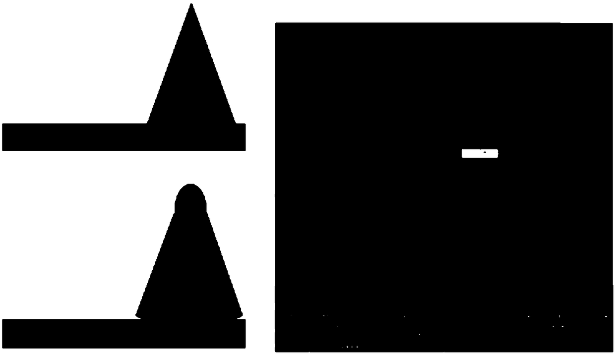

Image

  • Atomic force microscope probe manufacturing method possessing nanoscale spherical tip
  • Atomic force microscope probe manufacturing method possessing nanoscale spherical tip
  • Atomic force microscope probe manufacturing method possessing nanoscale spherical tip

Examples


Embodiment 1

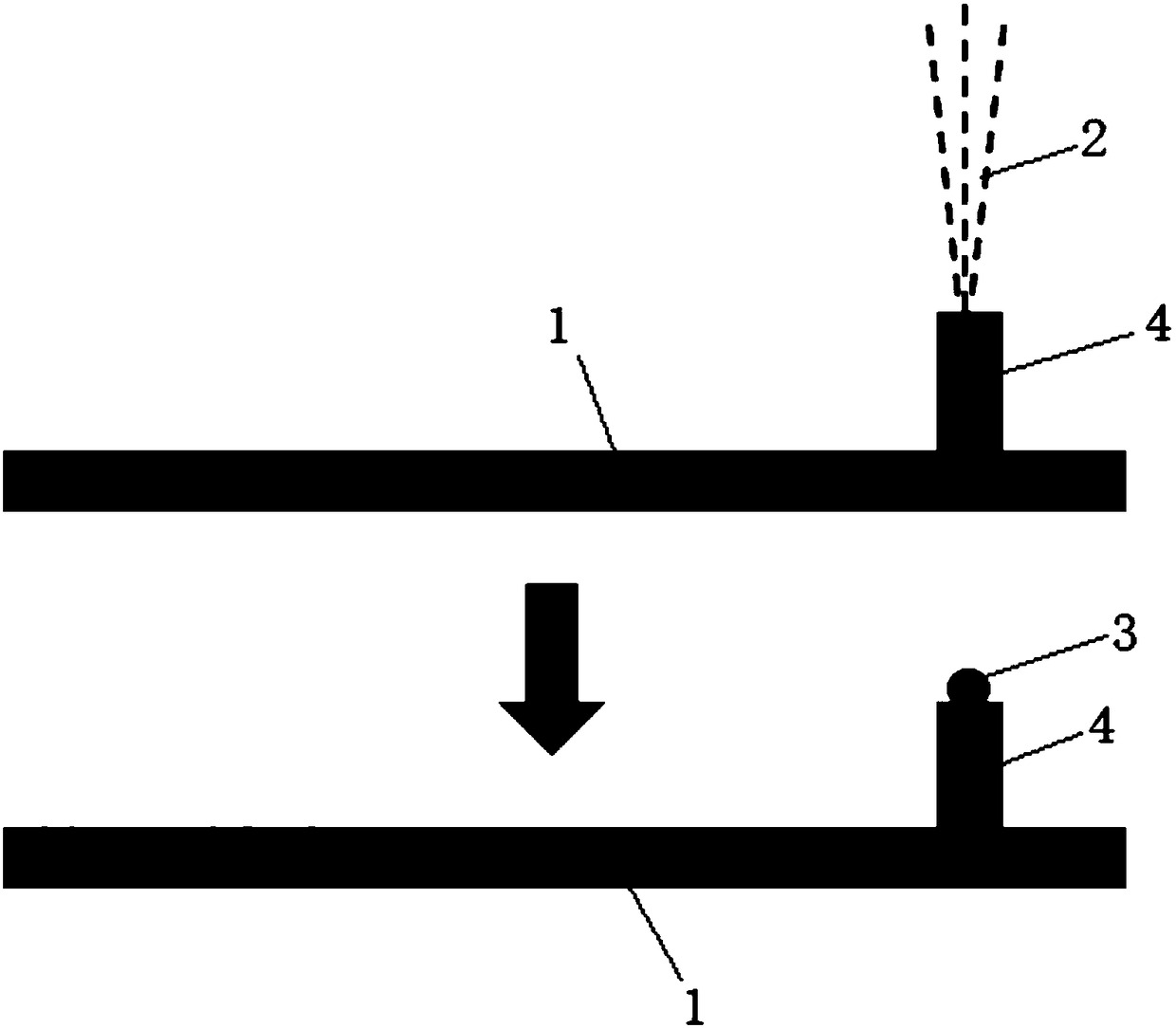
[0036] Such as image 3 , Figure 4 and Figure 5 As shown, a method for fabricating an atomic force microscope probe with a nanoscale spherical tip 3 includes the following steps:

[0037] S1. Take a micro-cantilever beam 1, set a protrusion on the surface of the micro-cantilever beam 1, and use the side where the protrusion is away from the micro-cantilever beam 1 as the substrate;

[0038] S2. Locating a particle injection position on the substrate through particle scanning substrate imaging;

[0039] S3. After applying a high voltage of 1KeV to 10MeV to helium ions, the particle beam is focused to form a high-energy particle beam 2. According to the size of the spherical tip 3, the high-energy particle beam 2 is quantitatively controlled by a timing switch valve in an area with a diameter of 250 nanometers. Inject the particle injection position within the range, so that the particle injection position bulges to form a spherical tip 3 (such as Figure 7 , the dose of h...

Embodiment 2

[0042] Such as Figure 6 As shown, a method for fabricating an atomic force microscope probe with a nanoscale spherical tip 3 includes the following steps:

[0043] S1. Take a micro-cantilever beam 1 and use the surface of the micro-cantilever beam 1 as a substrate;

[0044] S2. By calibrating the position of the high-energy particle beam 2 with the imaging position of the optical microscope or the imaging position of the atomic force microscope, and then positioning a particle injection position on the substrate through the imaging of the optical microscope or the imaging of the atomic force microscope;

[0045] S3. Apply a high voltage of 1KeV to 10MeV to the particles and then focus the particle beam to form a high-energy particle beam 2. According to the size of the spherical tip 3, the high-energy particle beam 2 is quantitatively controlled by a timing switch valve within the area of ​​250 nanometers in diameter. Inject the particle injection position into the particle ...


PUM


Abstract

The invention relates to an atomic force microscope probe manufacturing method possessing a nanoscale spherical tip. The method comprises the following steps of S1, taking a micro-cantilever beam, making an embossment on the surface of the micro-cantilever beam, taking one surface of the embossment, which is far away from the micro-cantilever beam, as a substrate; or taking the micro-cantilever beam, and taking the surface of the micro-cantilever beam as the substrate; S2, positioning one particle injection position at the substrate; and S3, quantifying one high energy particle beam in a set area range according to the size of the spherical tip which needs to be made and injecting into the particle injection position so that the particle injection position is plumped so as to form the spherical tip. In the invention, a molding speed is fast, a yield is high, cost is low, the method is suitable for industrialization, the controllability of a spherical tip diameter is good and the spherical tip is not easy to shed.

Description

technical field [0001] The invention belongs to the field of atomic force microscopes, in particular to a method for manufacturing an atomic force microscope probe with a nanoscale spherical tip. Background technique [0002] Atomic force microscopy is an important microscope for accurately measuring the surface morphology of samples, and has important applications in material surface morphology characterization, biological sample measurement, and nanoscale processing. The atomic force microscope probe is the core component of the atomic force microscope, usually consisting of a micro cantilever and a tip located at the free moving end of the micro cantilever. In order to be more accurate, reduce interference, and reduce damage to samples when measuring surface forces (especially biological samples), it is necessary to produce an atomic force microscope probe with a spherical tip. [0003] The existing AFM probe is coated on the surface of the needle tip to form a spherical...

Claims


Application Information

Patent Timeline
Patent Type & Authority Applications(China)
IPC IPC(8): G01Q70/16B81C1/00
CPCB81C1/00111G01Q70/16
Inventor 胡欢
Owner 胡欢
Learn More