Coal-fired flue gas treatment system

A processing system and technology for burning coal flue gas, which are used in gas treatment, combustion product treatment, combustion method, etc.

Active Publication Date: 2018-08-21
华创三立(北京)能源科技有限公司
View PDF4 Cites 1 Cited by
  • Summary
  • Abstract
  • Description
  • Claims
  • Application Information

AI Technical Summary

Problems solved by technology

[0004] Based on the above, this application provides a coal-fired flue gas treatment system for the collaborative removal of multi-pollutants in flue gas, wet plume treatment, and waste heat recovery after wet desulfurization

Method used


Image

  • Coal-fired flue gas treatment system
  • Coal-fired flue gas treatment system
  • Coal-fired flue gas treatment system

Examples


Embodiment Construction

[0047] In order to make the purpose, technical solution and advantages of the present application clearer, the coal-burning flue gas treatment system of the present application will be further described in detail through the following embodiments and in conjunction with the accompanying drawings. It should be understood that the specific embodiments described here are only used to explain the present application, not to limit the present application.

[0048] The coal-fired flue gas treatment system of the embodiment of the present application will be described in detail below with reference to the accompanying drawings.

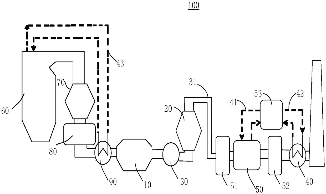
[0049] Please see attached figure 1 , the present application provides a coal-fired flue gas treatment system 100 . The coal-fired flue gas treatment system 100 includes an electrostatic precipitator 10 , a wet desulfurization device 20 , and a first heat recovery device 30 . The wet desulfurization device 20 is connected to the electrostatic precipitator ...


PUM


Abstract

The invention provides a coal-fired flue gas treatment system. Anti-condensation and anti-corrosion heat recovery devices and a heat pump are arranged in multiple places at the tail of a coal-fired flue gas eco-friendly island so as to achieve the effects of energy combination, water recovery and ultra-low emissions. The coal-fired flue gas treatment system is realized by reasonably arranging theheat recovery devices and the heat pump between an electrostatic dust collector, a wet desulphurization device and demisters and optimizing and controlling working condition parameters of the electrostatic dust collector, the wet desulphurization device and the demisters. The coal-fired flue gas treatment system has the technical characteristics that the synergistic effects and mutual combined effect improvement between heat exchange equipment and main devices and between the main devices is fully considered on the basis of the ultra-low emissions of the coal-fired flue gas treatment system, and the energy conservation, water conservation and emission reduction effects are remarkable.

Description

technical field [0001] The present application relates to a coal-fired flue gas treatment system. Background technique [0002] my country is a large coal-based energy consumer. According to the "Action Plan for Clean and Efficient Utilization of Coal (2015-2020)", by 2020, the proportion of thermal coal in coal consumption will increase to more than 60%, and the newly built coal in the eastern region will The flue gas pollutants of coal power generation units need to meet the ultra-low emission standard (that is, under the condition of the reference oxygen content of 6%, soot, SO 2 , NO x Emission concentrations are not higher than 10, 35, 50mg / m3 3 ), therefore, the whole industry is gradually accelerating the development of high-efficiency coal-fired power generation and upgrading to achieve clean and efficient utilization of coal. Coal-fired power plants are equipped with equipment such as desulfurization and denitrification, and electric dust removal, and have formed ...

Claims


Application Information

Patent Timeline
IPC IPC(8): F23J15/02F23J15/04F23J15/06F23J15/08B01D53/50B01D53/60B01D53/80
CPCB01D53/50B01D53/60B01D53/80B01D2258/0283F23J15/022F23J15/04F23J15/06F23J15/08F23J2215/20F23J2217/102Y02E20/30
Inventor 李水清王述浩陈红生段璐陈晟
Owner 华创三立(北京)能源科技有限公司
Why Eureka
Try Eureka