Composite microstructure current collector for lithium ion battery and preparation method of composite microstructure current collector

A composite microstructure, lithium-ion battery technology, applied in battery electrodes, secondary batteries, structural parts, etc., can solve the problems of excessive contact resistance between active materials and current collectors, affecting the overall performance of batteries, and low combined effective area. Achieve the effects of improving reversible capacity and capacity stability, low cost, and enhancing binding force

Active Publication Date: 2018-08-21
SOUTH CHINA UNIV OF TECH
View PDF4 Cites 4 Cited by
  • Summary
  • Abstract
  • Description
  • Claims
  • Application Information

AI Technical Summary

Problems solved by technology

The current commercialized copper foil current collectors are electrolytic copper foils with double-sided light, single-sided wool and double-sided wool, and their surface structure is too simple
The active material is directly coated on the current collector that lacks a special surface structure. The two are simply mechanically combined, which has the disadvantages of low bonding strength and low effective area, which leads to excessive contact resistance between the active material and the current collector, and further Cause problems such as low reversible capacity of the battery, poor rate performance and poor capacity stability, thus affecting the overall performance of the battery

Method used


Image

  • Composite microstructure current collector for lithium ion battery and preparation method of composite microstructure current collector
  • Composite microstructure current collector for lithium ion battery and preparation method of composite microstructure current collector
  • Composite microstructure current collector for lithium ion battery and preparation method of composite microstructure current collector

Examples


Embodiment 1

[0039] A composite microstructure current collector for lithium-ion batteries and a preparation method thereof, comprising the steps of:

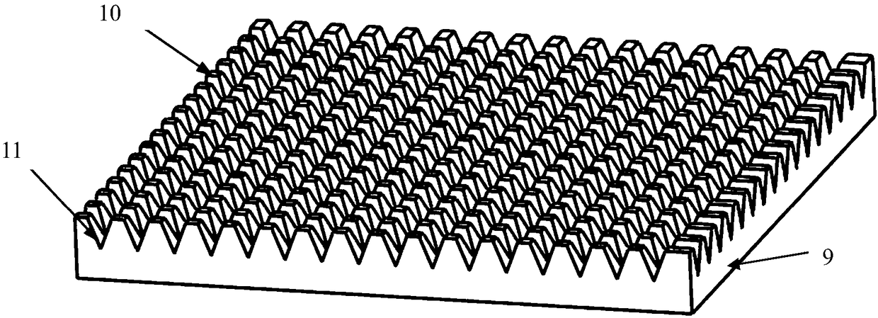
[0040] (1) Design of the tool: The material of the tool is W18Cr4V. The main tool angles include: rake angle α =40°, relief angle kappa =20°, extrusion blade inclination angle β =30° and forming angle θ =20°. Other tool parameters include tool width B 0 =20mm and thickness L t =4mm (see Figure 4 ).

[0041] (2) Surface pretreatment of the circular copper sheet: use sandpaper to polish the 0.5mm thick copper sheet to make both surfaces smooth. Then soak the copper sheet in the cleaning agent for the surface of the copper clad laminate and stir continuously for 5 minutes to make the two surfaces of the copper sheet smooth.

[0042] (3) Tool clamping and workpiece fixing: Clamp the plow cutting tool on the planer, adhere the round copper sheet to the stainless steel square table with metal 502 glue, then fix the square table on th...


PUM

PropertyMeasurementUnit
thicknessaaaaaaaaaa

Abstract

The invention discloses a composite microstructure current collector for a lithium ion battery and a preparation method of the composite microstructure current collector for the lithium ion battery. The composite microstructure current collector comprises a smooth bottom surface and a top surface with a composite microstructure; the top surface comprises a micro-convex table and grooves, and the micro-convex table is surrounded by the grooves; concave holes, scaly burrs and a sinking structure are arranged on the micro-convex table. The preparation method comprises the following steps: (1) designing a cutter and carrying out pretreatment on a copper sheet; (2) cutting a processing surface microstructure by a plow. The composite microstructure current collector for the lithium ion battery,disclosed by the invention, can effectively increase the surface area of the current collector to enhance the contact between active materials and the current collector, and improve the utilization ratio of the active materials and the conductivity of an electrode to increase the capacity of the battery, reduce the impedance of the battery, and improve the rate capability of the battery. The composite microstructures such as the grooves, the concave holes, the scaly burrs, the sinking structure and the like can limit acute volume changes of the active materials during the charging-dischargingprocess of the battery to prolong the service life of the battery and improve electrochemical properties of the reversible capacity, the cycling stability, the coulombic efficiency and the like of thebattery.

Description

technical field [0001] The invention relates to the technical field of lithium ion batteries, in particular to a composite microstructure current collector for lithium ion batteries and a preparation method thereof. Background technique [0002] Lithium-ion batteries have been around for less than 30 years. Compared with valve-regulated lead-acid batteries, rechargeable nickel-cadmium batteries or nickel-metal hydride batteries, lithium-ion batteries are characterized by their high unit energy density, wide application range and excellent large capacity. Advantages such as current discharge performance become the best among these secondary batteries. At the beginning of the new century, with the research and development of new energy-powered vehicles, the energy reform aimed at reducing environmental pollution caused by energy consumption and replacing the old energy structure based on fossil fuels is advancing, and the energy structure centered on lithium-ion batteries is b...

Claims


Application Information

Patent Timeline
Patent Type & Authority Applications(China)
IPC IPC(8): H01M4/80H01M10/0525B23P15/00
CPCH01M4/80H01M10/0525B23P15/00H01M4/70H01M4/661Y02E60/10H01M4/72
Inventor 袁伟邱志强潘保有罗健黄诗敏汤勇
Owner SOUTH CHINA UNIV OF TECH
Why Eureka
Try Eureka