

Differential phase pulse magnetic field electromagnetic continuous casting method
A pulsed magnetic field and phase technology, applied in the field of metal material processing, can solve the problems of limited electromagnetic range and effect, non-adjustable electromagnetic in the height direction, low electromagnetic utilization rate, etc., to achieve enhanced disturbance and stirring effect, enhanced stirring effect, mechanical Effect of improving performance and yield
- Summary
- Abstract
- Description
- Claims
- Application Information
AI Technical Summary
Problems solved by technology
Method used
Image

Examples
Embodiment 1
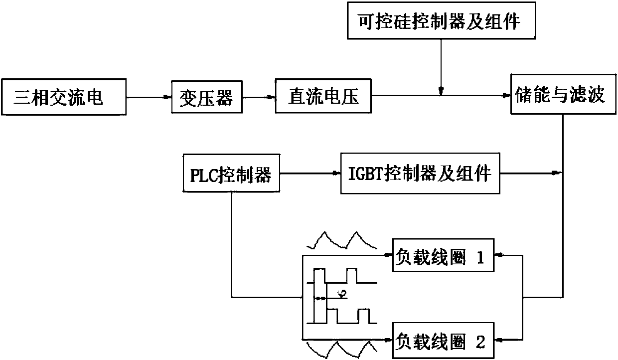
[0041] The principle of the phase difference pulse power supply system in the phase difference pulse magnetic field electromagnetic continuous casting method is as follows: figure 1 As shown, the phase pulse power supply system outputs the DC voltage through the input three-phase AC power through the transformer, and then passes through the rectification and filtering of the thyristor controller, thyristor components and electrolytic capacitors, passes through the IGBT trigger unit, and then passes through the non-polar capacitor and the load coil Parallel components form an LC oscillating circuit, and through the adjustment of the PLC controller, two sets of square wave pulse voltage and sawtooth pulse current with a phase angle difference of 90 degrees are output;
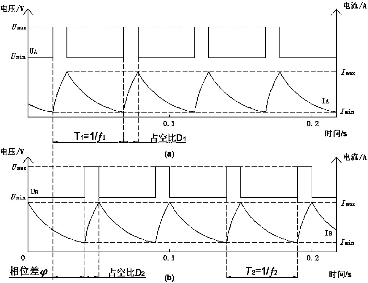
[0042] The typical voltage and current waveforms generated by the phase-difference pulse electromagnetic system are as follows: figure 2 As shown, two sets of typical pulse signals generated by the phase differe...
Embodiment 2
[0050] Carry out horizontal continuous casting, the principle of the phase difference pulse power supply system in the phase difference pulse magnetic field electromagnetic continuous casting method is the same as embodiment 1;
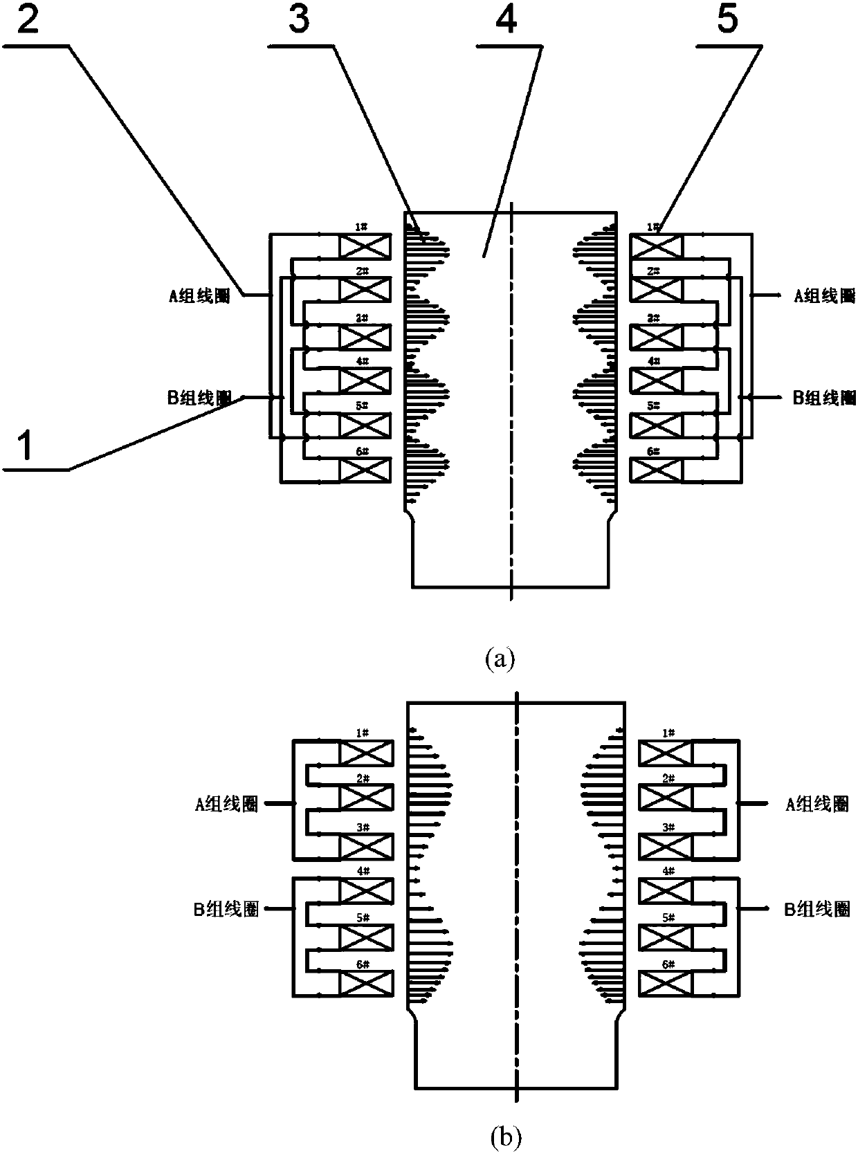
[0051] The device structure of the working mode of the phase difference pulse magnetic field electromagnetic continuous casting method is as follows Figure 5 As shown in (b), the metal melt enters the mold inner sleeve 20 (casting cavity) through the tundish 22. In order to prevent the metal melt from cooling down too quickly during the subcontracting process, a heating coil 23 is arranged outside the runner 26, and at the same time A magnetic field is applied to make the temperature distribution more uniform, to ensure that the molten metal maintains an appropriate temperature before entering the mold inner sleeve 20, to ensure that the Lorentz force can fully act on the molten metal 8, and to cool the molten metal 8 once by circulating cooling water...
PUM
 Abstract
Description
Claims
Application Information