Device and method for realizing automatic thickness ratio detection of composite plate

A detection device and automatic detection technology, applied in the field of sheet metal processing, can solve problems such as low efficiency, inaccurate detection results, and hidden dangers in the safety of composite panels, so as to improve efficiency and accuracy, improve product qualification rate, and reduce detection. cost effect

Active Publication Date: 2018-09-04
BEIJING XINGHANG MECHANICAL ELECTRICAL EQUIP
View PDF14 Cites 17 Cited by
  • Summary
  • Abstract
  • Description
  • Claims
  • Application Information

AI Technical Summary

Problems solved by technology

In this way, the missed inspection of a certain part of the composite board will lead to inaccurate detection results, which will bury hidden dangers in the safety of the composite board.
Moreover, the human error of the manual detection method is large and the efficiency is low
[0003] The patents represented by the announcement number CN 104122901 A titled "A Method for Controlling Plate Thickness" and the announcement number CN203881312 U titled "A Device for Automatic Thickness Detection of Plates" are based on the use of a set of symmetrical arrangements on the upper and lower sides of the plate. The range finder is used to detect the total thickness of the board, but none of them can realize the separa

Method used


Image

  • Device and method for realizing automatic thickness ratio detection of composite plate
  • Device and method for realizing automatic thickness ratio detection of composite plate
  • Device and method for realizing automatic thickness ratio detection of composite plate

Examples


Embodiment Construction

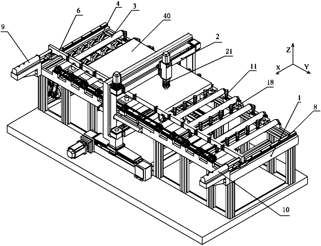
[0027]The implementation of the present invention will be described in further detail below in conjunction with the accompanying drawings. In order to briefly describe the technical solution of the present invention, the detailed description will only be carried out by dividing the composite board into three areas for detection. During actual detection, the detection area is divided according to the length of the composite board, and multiple Y-axis limit devices are installed as required.

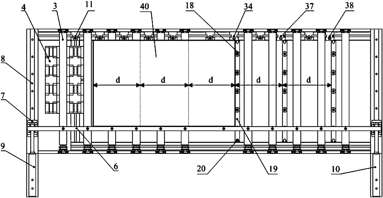
[0028] exist figure 1 with figure 2 In the schematic diagram of the device that can realize the automatic detection of the thickness ratio of the whole board surface of the composite board, cylindrical linear slide rails are arranged at the bottom of both sides of the bed width direction of the composite board conveying machine tool 1, and the three-coordinate instrument in the three-coordinate detection device 2 There are sliding bearings on both sides of the bracket, and the three-coor...


PUM


Abstract

The invention relates to a device capable of realizing automatic thickness ratio detection of the whole surface of a composite plate. The device comprises a composite plate conveying machine tool anda three-coordinate detecting device. The three-coordinate detecting device is connected with the composite plate conveying machine tool through a sliding bearing. The composite plate conveying machinetool is provided with an automatic plate positioning device which comprises X-axis and Y-axis direction positioning devices and a positioning auxiliary device. The three-coordinate detecting device comprises a three-coordinate meter, a laser-ultrasonic integrated probe and laser ranging. The method capable of realizing automatic thickness ratio detection of the whole surface of the composite plate comprises the steps that the laser-ultrasonic integrated probe of the three-coordinate meter is lowered to press against the surface of the composite plate; the ultrasonic and reflection waves of the interface of the base layer and the stratified layer of the composite plate is detected; and according to the detecting time of the reflection waves and the propagation sound velocity of the ultrasonic wave in the stratified layer material, the thickness of the stratified layer and the base layer is calculated. The device and the method have the advantages of comprehensive and accurate detection, high degree of automation, improved production efficiency and reduced cost.

Description

technical field [0001] The invention belongs to the technical field of plate processing, in particular to a plate detection device and detection method. Background technique [0002] Composite panels have excellent comprehensive performance and are widely used in shipbuilding industry, petrochemical, nuclear power and other fields. Thickness ratio (ratio of composite layer thickness to total thickness) is an important parameter related to the excellent performance of composite panels. In order to ensure the quality of composite panels, it is necessary to conduct comprehensive and accurate detection of the thickness ratio of composite panels. The traditional detection method is that the inspectors hold a micrometer to select a limited number of points on the outer side of the composite board for sampling inspection. Obviously, this method can only detect the exposed side of the composite board, but it is powerless to detect the thickness ratio of the central area. In this wa...

Claims


Application Information

Patent Timeline
IPC IPC(8): G01B17/02G01B11/02
CPCG01B11/026G01B17/02
Inventor 金贺荣韩民峰
Owner BEIJING XINGHANG MECHANICAL ELECTRICAL EQUIP
Why Eureka
Try Eureka