
Solar-blind ultraviolet light detecting device

A detection device and ultraviolet light technology, which are applied in measurement devices, photometry, optical radiation measurement, etc., can solve the problems of low sensitivity of ultraviolet light detectors, limit solar-blind ultraviolet light detection, and low emission power, etc., and achieve improved detection. Sensitivity, great economic value, low dark current effect

Active Publication Date: 2018-09-04
NANJING UNIV OF POSTS & TELECOMM
View PDF5 Cites 5 Cited by
  • Summary
  • Abstract
  • Description
  • Claims
  • Application Information

AI Technical Summary

Problems solved by technology

At present, the emission power of solar-blind ultraviolet light sources is very small (about mW level), and the sensitivity of ultraviolet light detectors is low (usually 0.01-0.05A / W, which is much lower than the 0.3-0.6A of visible light / near-infrared detectors. / W), thus greatly limiting the detection of solar-blind UV light

Method used


Image

  • Solar-blind ultraviolet light detecting device
  • Solar-blind ultraviolet light detecting device
  • Solar-blind ultraviolet light detecting device

Examples


Embodiment 1

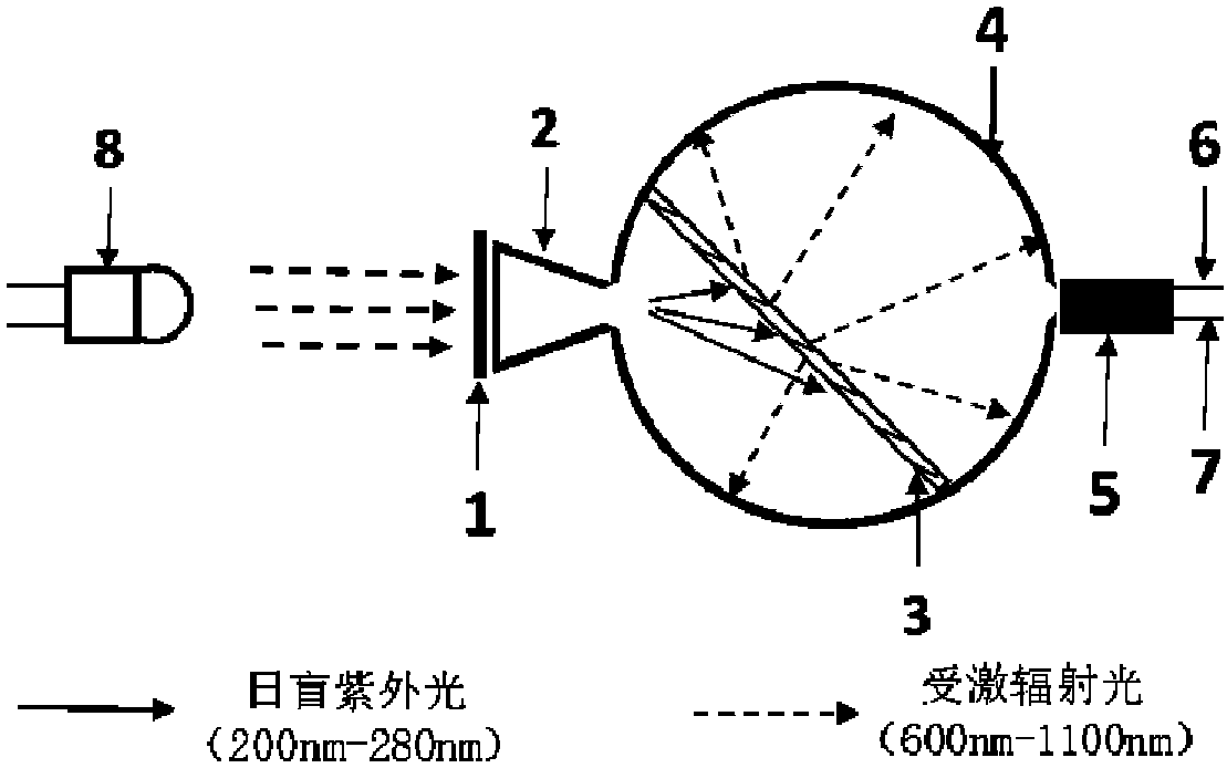
[0018] like figure 1 As shown, a solar-blind ultraviolet light detection device is provided with a filter 1 at the incident window at the front end of the wide-field collector 2, and the rear end of the wide-field collector 2 is connected to the incident light window of the integrating sphere 4; inside the integrating sphere 4 Place the quantum tailoring fluorescent glass 3. The two sides of the quantum tailoring fluorescent glass 3 correspond to the incident window and the exit window of the integrating sphere 4 respectively. The detection windows of the photomultiplier tubes 5 are closely connected.

[0019] The filter 1 of the present invention will filter all the light in the non-detection wavelength region, and only keep the light in the desired detection wavelength range, that is, the transmission wavelength range of the filter 1 can be adjusted to limit the detection wavelength range, but the transmission of the filter The wavelength range should be included in the wav...

Embodiment 2

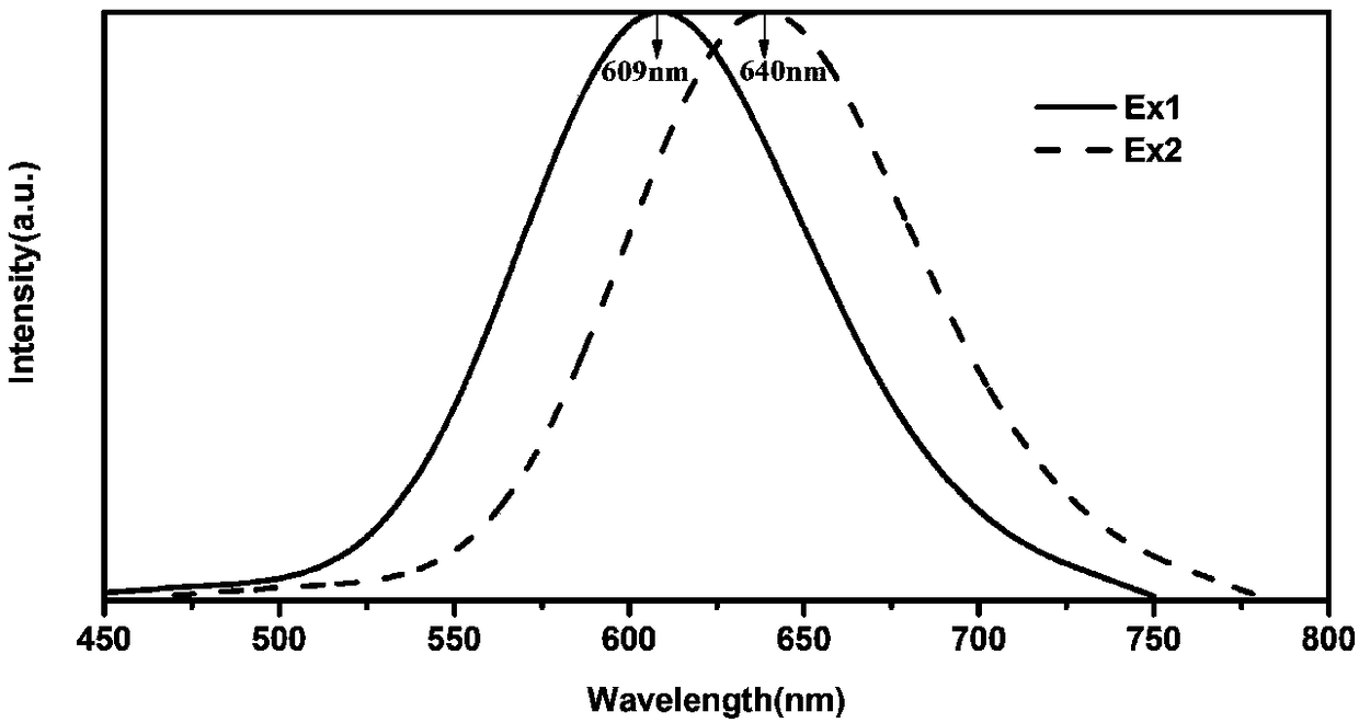
[0024] The difference between embodiment 2 and embodiment 1 is that the quantum tailoring fluorescent glass 3 whose substrate is silicate is selected in this embodiment, the stimulated emission light is monochromatic light and the peak value of the stimulated emission spectral power curve is at 640nm, and its Stimulated emission spectrum such as figure 2 Shown in the Ex2 curve. The remaining features of embodiment 2 are the same as embodiment 1.

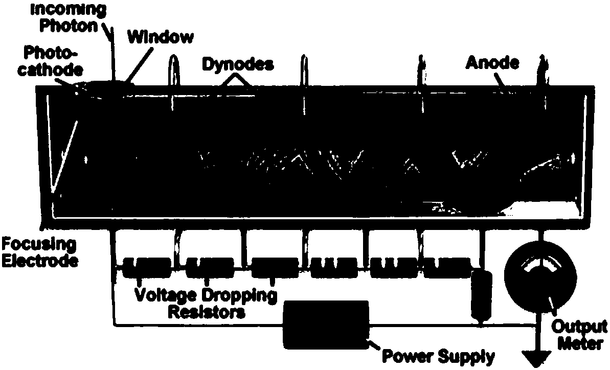
[0025] As described in Embodiment 1, the fluorescent glass is cut and polished to a size that can fit inside the integrating sphere 4 , and the edge is attached to the inner surface of the integrating sphere 4 . Attach a low-pass filter with a cutoff wavelength of 280 nm to the outer surface of the incident window of the integrating sphere 4 . response curve as Figure 4 The photomultiplier tube 5 shown is placed in the exit window of the integrating sphere 4 , and its detection window is close to the outer surface of the exit wi...


PUM


Abstract

The invention discloses a solar-blind ultraviolet light detecting device, which uses the quantum tailoring technology to complete the wavelength conversion and photon number amplification function ofprobe light. The quantum-cut fluorescent glass in an integrating sphere absorbs 200 nm to 280 nm of solar-blind ultraviolet photons, and is stimulated to radiate 2 to 3 times the number of long-wavelength photons; an exit window end of the integrating sphere is connected to a photomultiplier tube of an active device, the output current of the photomultiplier tube is proportional to the number of the received photons, and the sensitivity to the visible band light is 2 to 10 times that of the solar-blind ultraviolet light. The filtering effect of a filter arranged on an incident window of the integrating sphere can strictly limit the detection wavelength range, and can multiply the sensitivity of detection of solar-blind ultraviolet light.

Description

technical field [0001] The invention discloses a photoelectric conversion device, in particular to a sun-blind ultraviolet light detection device. Background technique [0002] Solar-blind ultraviolet light (UVC) usually refers to electromagnetic radiation with a wavelength of 200nm-280nm. Due to the strong absorption of ultraviolet light by ozone and oxygen and the strong scattering of ultraviolet light, natural solar-blind ultraviolet light near the surface of the earth hardly exists, that is, This means that there is very little unnatural interference from the sun-blind UV light on the surface. Therefore, solar-blind ultraviolet light detection technology has attracted extensive attention from researchers in military and civilian fields, such as missile guidance and early warning, ultraviolet communication in military, flame detection in civilian aspects, and ultraviolet measurement in water purification process, etc. [0003] The main function of the detector is to comp...

Claims


Application Information

Patent Timeline
IPC IPC(8): G01J1/00G01J1/02G01J1/04
CPCG01J1/00G01J1/02G01J1/04
Inventor 韦玮尤波郑锐林杨宇
Owner NANJING UNIV OF POSTS & TELECOMM
Learn More