Tin collecting plate and manufacturing method thereof

A manufacturing method and technology of tin sheet, which is applied in the direction of manufacturing tools, auxiliary devices, coatings, etc., can solve the problems of low service life of coatings, improve the ability to resist high-temperature oxidation pollution, and have low requirements for substrate surface roughness and low cost. Effect

Inactive Publication Date: 2018-09-14
UNITED AUTOMOTIVE ELECTRONICS SYST
View PDF7 Cites 0 Cited by
  • Summary
  • Abstract
  • Description
  • Claims
  • Application Information

AI Technical Summary

Problems solved by technology

[0009] The purpose of the present invention is to provide a tin receiving sheet and its manufacturing method to solve the problem of low service life of the coating of the existing tin receiving sheet and its manufacturing method

Method used


Image

  • Tin collecting plate and manufacturing method thereof
  • Tin collecting plate and manufacturing method thereof

Examples


Embodiment 1

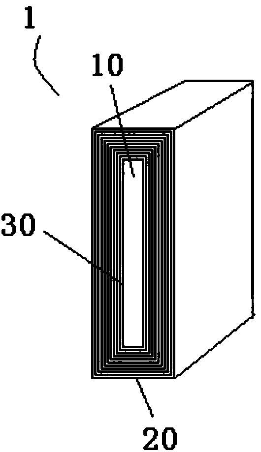
[0045] Such as figure 1 As shown, a tin receiving sheet 1 is provided in this embodiment, and the tin receiving sheet 1 includes a substrate 10, a plurality of activation layers 30, and a plurality of immersion coating layers 20, wherein the outer surface of the substrate 10 is sequentially The activation layer 30 and the immersion coating layer 20 are formed alternately, the outermost layer is the immersion coating layer 20, that is, the substrate 10 is in the innermost layer, the activation layer 30 and the immersion coating layer 20 are stacked alternately, the activation layer 30 is close to the substrate, and the final The outer layer is an immersion plating layer 20 .

[0046]Specifically, in the tin receiving sheet 1, the surface of the outermost immersion coating 20 of the tin receiving sheet 1 is a mirror surface, and the mirror surface is to cover the knife marks or unevenness on the surface of the substrate 10, so as to avoid high temperature during use. Oxidation ...

Embodiment 2

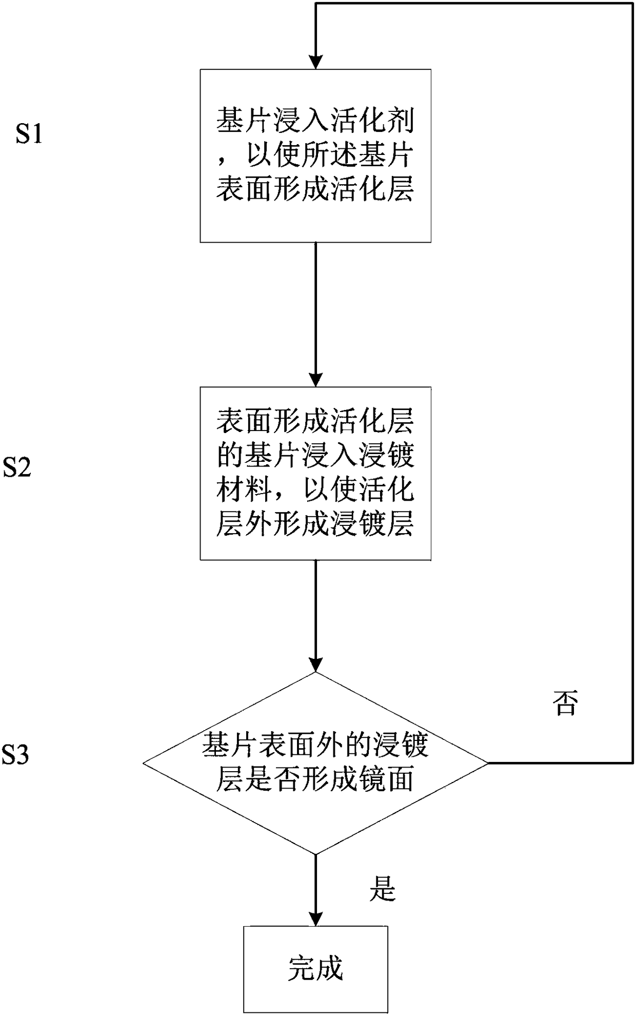
[0050] Such as figure 2 As shown, the present embodiment provides a method for making tin receiving sheet, figure 2 It is a flow chart of the manufacturing method of the tin receiving sheet in this embodiment. The manufacturing method of the tin receiving sheet has the following steps:

[0051] S1: The substrate is immersed in an activator to form an activation layer on the surface of the substrate;

[0052] S2: The substrate with the active layer formed on the surface is immersed in the immersion plating material to form an immersion plating layer outside the active layer;

[0053] S3: Determine whether the immersion coating layer outside the substrate surface forms a mirror surface, if the immersion coating layer outside the substrate surface does not form a mirror surface, then perform steps S1 to S3 again, if the immersion coating layer outside the substrate surface forms a mirror surface, then Finish.

[0054] Specifically, such as figure 2 As shown, steps S1, S2 ...


PUM

PropertyMeasurementUnit
Surface roughnessaaaaaaaaaa

Abstract

The invention provides a tin collecting plate and a manufacturing method thereof. The tin collecting plate comprises a substrate, a plurality of activating layers and a plurality of dip plating layers, wherein the activating layers and the dip plating layers are successively and alternately formed on the outer surface of the substrate; and the outermost layer is the dip plating layer. The manufacturing method of the tin collecting plate has the following steps: removing rust of the substrate, namely low-carbon steel; then soaking the substrate in an activating agent, namely rosin as a soldering flux; soaking the substrate in a dip plating material, namely tin silver copper or tin silver; and repeatedly soaking the substrate in the soldering flux and the dip plating material until the surface of the tin collecting plate has a mirror effect, wherein the substrate generally requires to be soaked into the soldering flux and the dip plating material repeatedly for five times to ten times. The surface of the tin collecting plate is smooth, welding without stopping due to high-temperature oxidation is unlikely to cause, a plated layer is thick, and is bound to the substrate strongly, wettability is unlikely to decline, and the service life is long. The manufacturing method of the tin collecting plate is simple in process and low in cost, process time only needs several hours, and industrial waste pollution cannot be caused.

Description

technical field [0001] The invention relates to the technical field of electronic printed circuit board welding, in particular to a tin receiving sheet and a manufacturing method thereof. Background technique [0002] Soldering of through-hole components In large-scale industrial manufacturing, several soldering techniques such as wave soldering and selective soldering are mainly used. [0003] Wave soldering has the advantages of high production efficiency and large output in the manufacture of through-hole component circuit boards, so it used to be the most important welding equipment in the automated mass production of electronic products. However, there are certain limitations in its application: different solder joints on the same circuit board may have different soldering parameters due to their different characteristics (such as heat capacity, pin spacing, tin penetration requirements, etc.), This makes it difficult for wave soldering to fully meet the soldering requ...

Claims


Application Information

Patent Timeline
IPC IPC(8): B23K3/08H05K3/34C23C2/02B23K101/42
CPCB23K3/08C23C2/02H05K3/34
Inventor 田唤啸史松青葛文豪袁飞
Owner UNITED AUTOMOTIVE ELECTRONICS SYST
Why Eureka
Try Eureka