Hardware circuit of pain electric pulse therapy instrument

A hardware circuit and therapeutic device technology, applied in the field of medical systems, can solve problems such as inconsistent electrical stimulation responses, interruption of pain information transmission, and inability to output specific electrical pulse signals.

Active Publication Date: 2018-09-28
汉中秦航精密机电有限公司
View PDF6 Cites 6 Cited by
  • Summary
  • Abstract
  • Description
  • Claims
  • Application Information

AI Technical Summary

Problems solved by technology

Electrotherapy mainly includes direct current therapy, direct current drug iontophoresis therapy, and low. In addition to a large amount of water in the human body, there are also many conductive electrolytes and non-conductive dielectrics. Therefore, the human body is actually a body with both resistance and capacitance properties. Complex conductor, which is the material basis of electrotherapy. The body responds differently to different types of electrical stimulation, and the treatment mechanism is also different. Low-frequency current can change the membrane potential of nerve and muscle cells, making them excited...

Method used


Image

  • Hardware circuit of pain electric pulse therapy instrument
  • Hardware circuit of pain electric pulse therapy instrument
  • Hardware circuit of pain electric pulse therapy instrument

Examples


Embodiment 1

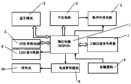
[0028] Embodiment 1: A hardware circuit of a pain electric pulse therapy instrument, at least including a microcontroller 1, a Bluetooth module 2, a boost circuit 3, a pulse forming circuit 4, a USB bridge circuit 5, an LED indicating circuit 6, and a power management module 9 , button module 8, triaxial acceleration sensor 7 and lithium battery 10, it is characterized in that: described microcontroller 1 output terminal is respectively connected bluetooth module 2, step-up circuit 3, pulse forming circuit 4, USB bridging circuit 5, LED indication Circuit 6, power management module 9, button module 8, input terminal of triaxial acceleration sensor 7, wherein output terminal of boost circuit 3 is connected to input terminal of pulse forming circuit 4, output terminal of power management module 9 is connected to input terminal of lithium battery 10, power management The lithium battery 10 in the module 9 supplies power to each module circuit, the power management module 9 supplie...

Embodiment 2

[0031] Such as Figure 8 As shown, the microcontroller 1 adopts a single-chip microcomputer whose model is MSP430.

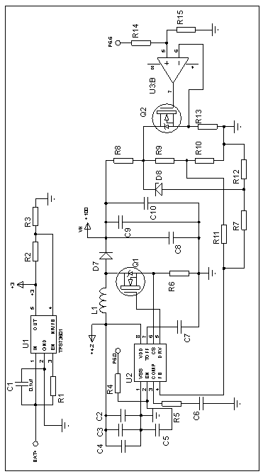
[0032] Select power management and microcontroller 1 core devices with extremely low power consumption. In the design of the circuit part, the MSP430F169IPM with low operating voltage and low power consumption in the MSP430 series microcontroller 1 product family is selected as the core control chip of this product. At the same time, the ultra-low dropout and ultra-low power consumption power supply chip TPS73601DBVT is selected to realize power management. This chip can work under extremely low input-output pressure difference, and its own power consumption is extremely low. For other peripheral circuits, the microcontroller 1 controls the on-off of the MOS tube to realize the dynamic management of the power supply, and only supplies power when the relevant unit circuits are working.

Embodiment 3

[0034] Such as figure 2 and Figure 8 As shown, the boost circuit 3 uses a TPS73601 single-chip microcomputer, the circuit is connected to the microcontroller 1 through the P6.6 pin, and the P6.0 port of the microcontroller 1 transmits the control signal to the U2 chip in the boost circuit 3 .

[0035] Under the control of the microcontroller 1, the boost circuit 3 generates PWM output from a dedicated DC-DC boost chip, which excites the high-frequency power MOS boost tube, and passes through components such as energy storage inductors, fast recovery rectifier diodes, and energy storage filter capacitors. , to output a suitable voltage under the control of the microcontroller 1 to supply power to the pulse forming circuit 4 .

[0036] The LDO chip U1 is the core chip of the power management module 9. Due to the limited capacity of the battery, the output voltage will gradually decrease with the prolongation of the use time. Choose TPS73601 as the LDO chip, the voltage regul...


PUM


Abstract

The invention relates to a hardware circuit of a pain electric pulse therapy instrument. The hardware circuit comprises a microcontroller, a Bluetooth module, a boosted circuit, a pulse forming circuit, a USB bridge circuit, an LED indicating circuit, a power management module, a button module, a three-axis acceleration sensor and a lithium battery, wherein an output pin of the microcontroller isconnected to input ends of the Bluetooth module, boosted circuit, pulse forming circuit, USB bridge circuit, LED indicating circuit, power management module, button module and three-axis accelerationsensor separately, an output end of the boosted circuit is connected to the input end of pulse forming circuit, and an output end of the power management module is connected to the input end of the lithium battery. The hardware circuit of the pain electric pulse therapy instrument has the advantages that the used electric pulse frequency and pulse width are different from those of existing products, and a user can select the treatment intensity according to his/her own symptoms and use effects.

Description

technical field [0001] The invention relates to the technical field of medical systems, in particular to a hardware circuit of a pain electric pulse therapeutic apparatus. Background technique [0002] The purpose of pain treatment is to reduce or terminate pain attacks, relieve accompanying symptoms, and prevent pain recurrence. Treatment methods include drug therapy and non-drug therapy. Drug therapy has a certain degree of toxic and side effects, and patients may experience adverse reactions. [0003] Non-drug treatment is mainly physical therapy, which can use electrotherapy, magnetic therapy, psychological counseling to relieve stress, etc. Compared with drug treatment, its biggest advantage is that there will be no toxic side effects of drugs. [0004] In terms of electrotherapy, electrodes are usually placed on certain parts of the human body surface to apply electrical signals. Electrodes placed on the surface of the body are generally far away from the chest, and t...

Claims


Application Information

Patent Timeline
IPC IPC(8): A61N1/36
CPCA61N1/36021A61N1/3603
Inventor 李文华王汉文袁华魏向阳尹继武
Owner 汉中秦航精密机电有限公司
Why Eureka
Try Eureka