Flue gas desulfurizing tower and flue gas dust removal, desulfurization and wastewater treatment method

A technology for desulfurization towers and flue gas, which is applied in the fields of flue gas desulfurization towers, flue gas dust removal, desulfurization and wastewater treatment. It can solve problems such as too many equipments, unsatisfactory flue gas emission indicators, shutdown or demolition and reconstruction, and achieve high dust removal efficiency. , Reduce device investment and operating costs, and reduce energy consumption

Active Publication Date: 2018-10-09
CHINA PETROLEUM & CHEM CORP +1
View PDF12 Cites 4 Cited by
  • Summary
  • Abstract
  • Description
  • Claims
  • Application Information

AI Technical Summary

Problems solved by technology

The above-mentioned wet desulfurization technology includes flue gas desulfurization, desulfurization wastewater oxidation treatment or regeneration unit. The process is long, there are many equipments, and the floor area is large, which seriously restricts the construction and upgrading of dust removal and desulfurization devices. Some catalytic devices and coal-fired Boilers cannot be upgraded due to lack of sufficient space, resulting in smoke emission indicators that cannot meet the current national standards and have to be shut down or demolished and rebuilt

Method used


Image

  • Flue gas desulfurizing tower and flue gas dust removal, desulfurization and wastewater treatment method
  • Flue gas desulfurizing tower and flue gas dust removal, desulfurization and wastewater treatment method
  • Flue gas desulfurizing tower and flue gas dust removal, desulfurization and wastewater treatment method

Examples


Embodiment

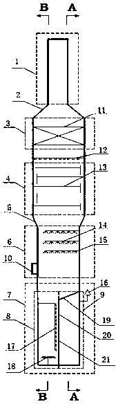
[0082] A flue gas dedusting and desulfurization tower, from top to bottom are the flue gas discharge area 1, the mist removal area 3, the tower area 4, the spray area 6 and the waste water treatment area 7, the flue gas discharge area 1 and the mist removal area 3 It is connected by a cone-shaped diameter 2, and below the demisting area 3 is a tray area 4, and the tray area 4 and the spray area 6 are connected by an inverted cone-shaped diameter 5, and below the spray area 6 is a waste water treatment area 7. The chimney 1 has a diameter of 3m, the tower upper shell 3 has a diameter of 9m, and the tower lower shell 7 has a diameter of 6m.

[0083] A wet electrostatic demister 11 is arranged in the demisting area 3, a liquid distributor 12 is arranged under the wet electrostatic demister 11, a tray area 4 is arranged under the liquid distributor 12, and a total of 4 layers of trays are arranged in the tray area 4. A sieve tray is selected; the spray area 6 is provided with thre...


PUM

PropertyMeasurementUnit
heightaaaaaaaaaa
diameteraaaaaaaaaa
diameteraaaaaaaaaa

Abstract

The invention discloses a flue gas desulfurizing tower and a flue gas dust removal, desulfurization and wastewater treatment method. The flue gas desulfurizing tower sequentially comprises a flue gasexhaust area, a demist area, a tower tray area, a spraying area and a wastewater treatment area from top to bottom; the flue gas exhaust area and the demist area are connected through a cone deformation diameter, the tower tray area and the spraying area are connected through an inverted cone deformation diameter; the wastewater treatment area is divided by a vertical partition plat I from the center into an oxidation flocculation area and a circulation clear liquid area, the circulation clear liquid area is completely separated from the oxidation flocculation area and the spraying area through a partition plate II from the top part of the circulation clear liquid area; and the vertical partition plate I is provided with a filter medium. The flue gas is subjected to dust removal, desulfurization and wastewater treatment in one tower, the flue gas is used to stir the wastewater to implement the operations of oxidation flocculation and concentration, the difference of the liquid levels of the two sides of the vertical partition plate is used as a driving force to filter the desulfurization wastewater, the occupied area is greatly reduced, the costs for the construction and transformation of the device and the operation cost of the device are obviously lowered.

Description

technical field [0001] The invention belongs to the field of industrial waste gas purification, and relates to a flue gas desulfurization tower and flue gas dust removal, desulfurization and wastewater treatment methods. Background technique [0002] Sulfur dioxide and dust are contained in the flue gas of coal-fired boilers and the regenerated flue gas of catalytic cracking catalysts. Sulfur dioxide and dust are the main components of air pollutants. Sulfur dioxide is the main cause of acid rain, and dust with smaller particle sizes is the smog One of the culprits. [0003] Environmental pollution is becoming more and more serious, smog incidents occur frequently, and the country pays more and more attention to environmental protection. In recent years, a series of environmental protection laws and regulations, national standards, and management methods have been issued. GB 13223-2011 "Emission Standard of Air Pollutants for Thermal Power Plants" stipulates: coal-fired boi...

Claims


Application Information

Patent Timeline
Patent Type & Authority Applications(China)
IPC IPC(8): B01D53/78B01D53/80B01D53/50B01D50/00C02F9/04
CPCB01D47/021B01D47/06B01D53/50B01D53/78B01D53/80B01D2247/10B01D2258/0283B01D2259/126C02F1/001C02F1/52C02F1/72C02F9/00C02F2103/18
Inventor 李磊刘忠生李欣金平王昊辰韩天竹
Owner CHINA PETROLEUM & CHEM CORP
Why Eureka
Try Eureka