Horizontal push-flow anaerobic dry fermentation device and process for organic waste

A technology of organic waste and dry fermentation device, applied in biochemical cleaning device, enzymology/microbiology device, bioreactor/fermenter combination, etc., can solve the problem of affecting gas production, low volume gas production rate and waste of resources and other problems, to ensure the retention period, improve the yield, and improve the gas production rate.

Pending Publication Date: 2018-10-16
黑龙江乾进能源科技有限公司
View PDF0 Cites 4 Cited by
  • Summary
  • Abstract
  • Description
  • Claims
  • Application Information

AI Technical Summary

Problems solved by technology

[0002] Among the existing anaerobic fermentation technologies for industrialized continuous production, most of them adopt continuous stirred reactor system CSTR process and the main body is fully mixed anaerobic digester. Most of these domestic processes require the dry matter concentration to be below 10%. The role of the agitator can make the biogas slurry circulate. In the circulating flow, the floating material can be pressed down by stirring or using the overturned water flow to prevent crusting. Once the crusting will obviously inhibit the gas production, the CSTR process produces two Problem: 1. The concentration of dry matter should not be too high, otherwise the biogas slurry will not flow smoothly and there will be suspended matter crusting, and low concentration will obtain a lower volumetric gas production rate. 2. The full-mixing process will quickly Mix the newly added material with the original material in the tank. During the daily discharge process, the newly added material will always be discharged, which wastes resources and affects gas production. 3. The low dry matter concentration makes the organic waste Heavier substances precipitate, and the sediment layer will affect the conduction of the heating system and the normal operation of the discharge system, so it is necessary to clean the tank regularly
[0003] According to the NY / T2142-2012 specification for straw biogas engineering process design, the volumetric gas production rate is required to be above 0.8-1.0m3 / (m3·d), and the existing large-scale biogas projects that use agricultural and animal husbandry waste as raw materials do not exceed this standard. In actual production, only the normal gas production rate per ton is ensured at the same time (the biogas production per ton of dry corn stalks is 300m 3 ) the volumetric gas production rate exceeds 2.0m3 / (m3·d) to obtain income. To ensure the gas production per ton, the residence period of the material in the tank is the key. Only when the material in the fermentation tank moves step by step can the unit be guaranteed The residence time of the material in the tank and the fermentation cycle are fixed, so only by increasing the dry matter concentration can more feed be fed to obtain a higher volumetric gas production rate. The existing high-concentration fermentation process involved is garage-style fermentation. This process is packed After fermentation, the biogas residue needs to be removed and filled again, which cannot form continuous gas production and is mainly operated manually, which is not suitable for large-scale industrial continuous production

Method used


Image

  • Horizontal push-flow anaerobic dry fermentation device and process for organic waste
  • Horizontal push-flow anaerobic dry fermentation device and process for organic waste
  • Horizontal push-flow anaerobic dry fermentation device and process for organic waste

Examples


Embodiment Construction

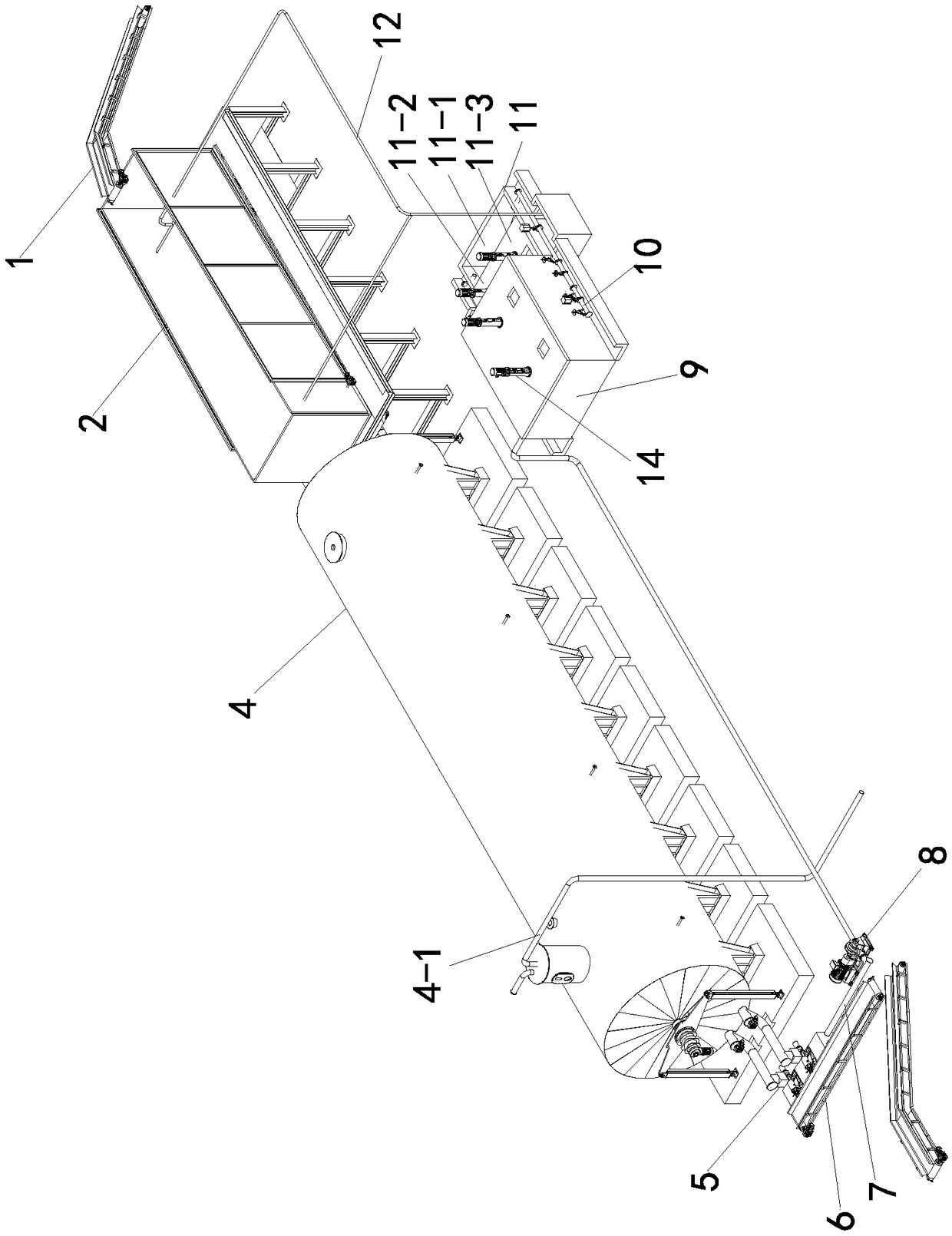
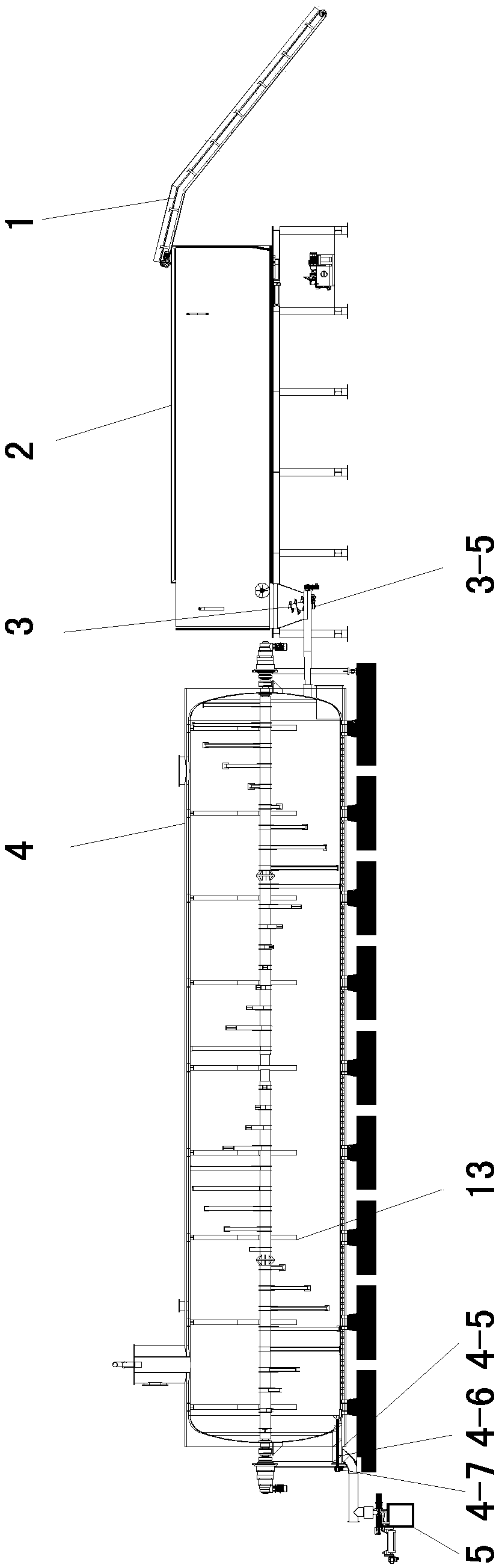
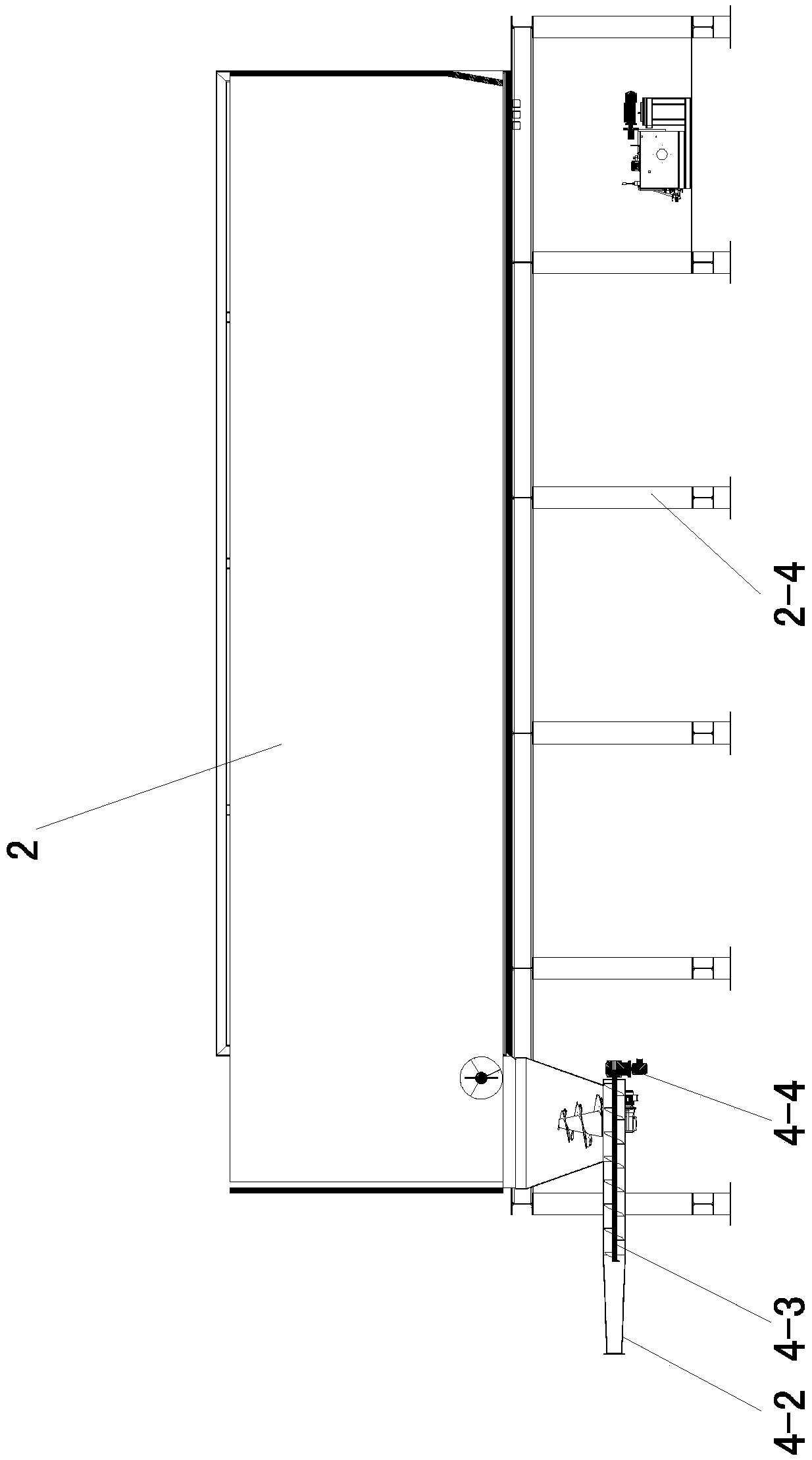
[0038] Such as Figure 1 to Figure 16As shown, a horizontal plug-flow anaerobic dry fermentation device for organic waste, including conveyor belt 1, pretreatment tank 2, feeder 3, anaerobic fermentation tank 4, press 5, conveyor belt 2 6, biogas liquid conduit 7, biogas slurry tank 9, delivery pipe 10, cow dung tank 11, water spraying pipeline 12 and plug-flow stirring shaft 13; the conveyor belt 1 transports the organic waste to the pretreatment tank 2 for stacking and retting, The feed end of described pretreatment pool 2 and the discharge end are all provided with drenching pipeline 12, and the discharge end of pretreatment pool 2 is provided with feeder 3, and described feeder 3 and anaerobic fermentation tank 4 The feed port is connected and the organic waste is transported to the anaerobic fermentation tank 4 for fermentation, and the biogas output pipe 4-1 provided with the anaerobic fermentation tank 4 is connected to an external gas transmission line to output the bi...


PUM


Abstract

The invention relates to a horizontal push-flow anaerobic dry fermentation device and process for organic waste, and belongs to the technical field of anaerobic fermentation. The concentration of drymatter in a tank can be increased to 30%-60%, heat consumption is effectively reduced, and gas production rate is increased. Water spraying pipes are arranged at a feed end and a discharge end of a pretreatment pool, a feeder is arranged at the discharge end of the pretreatment pool and communicated with feed ports of an anaerobic fermentation tank, discharge ports of the anaerobic fermentation tank are communicated with inlets of pressers, a conveyor belt II is arranged in the position of the pressers and conveys biogas residues discharged from solid outlets of the pressers outwards, a biogasslurry tank conveys biogas slurry into a cow dung tank through a conveying pipe, the cow dung tank is communicated with inlets of the water spraying pipes, and a push-flow stirring shaft is arrangedin the anaerobic fermentation tank. The concentration of the dry matter inside can be increased to 30%-60% by the anaerobic fermentation tank, heat consumption is effectively reduced, the gas production rate is increased and the yield is increased.

Description

technical field [0001] The invention belongs to the technical field of anaerobic fermentation, in particular to a horizontal plug-flow anaerobic dry fermentation device and process for organic waste. Background technique [0002] Among the existing anaerobic fermentation technologies for industrialized continuous production, most of them adopt continuous stirred reactor system CSTR process and the main body is fully mixed anaerobic digester. Most of these domestic processes require the dry matter concentration to be below 10%. The role of the agitator can make the biogas slurry circulate. In the circulating flow, the floating material can be pressed down by stirring or using the overturned water flow to prevent crusting. Once the crusting will obviously inhibit the gas production, the CSTR process produces two Problem: 1. The concentration of dry matter should not be too high, otherwise the biogas slurry will not flow smoothly and there will be suspended matter crusting, and...

Claims


Application Information

Patent Timeline
IPC IPC(8): C12M1/38C12M1/36C12M1/34C12M1/16C12M1/107C12M1/02C12P5/02C02F11/04
CPCC12M21/04C12M21/16C12M23/10C12M27/06C12M29/18C12M33/16C12M41/06C12M41/12C12M41/34C12M45/06C12P5/023Y02E50/30
Inventor 李多
Owner 黑龙江乾进能源科技有限公司
Why Eureka
Try Eureka