Method of Repairing the Outlet Edge of the Runner Blade of Francis Turbine

A technology for runner blades and blade outlets, which is applied in the field of edge modification of the outlet of Francis turbine runner blades, which can solve the problems of unable to prevent or eliminate the whistling of turbines and cracks of runner blades, so as to avoid the occurrence of blade cracks and ensure fatigue The effect of strength and simplification of the repair process

Active Publication Date: 2020-07-24
DONGFANG ELECTRIC MACHINERY
View PDF5 Cites 0 Cited by
  • Summary
  • Abstract
  • Description
  • Claims
  • Application Information

AI Technical Summary

Problems solved by technology

[0008] The method disclosed in this patent document for alleviating the pressure pulsation hazard in the vaneless zone of the Francis pump turbine is proposed on the basis of the cause of the pressure pulsation in the vaneless zone. Prevent or eliminate the howling noise of the turbine and the cracks of the runner blades caused by the hydraulic elastic resonance of the blades induced by the Karman vortex street at the runner outlet

Method used


Image

  • Method of Repairing the Outlet Edge of the Runner Blade of Francis Turbine
  • Method of Repairing the Outlet Edge of the Runner Blade of Francis Turbine
  • Method of Repairing the Outlet Edge of the Runner Blade of Francis Turbine

Examples


Embodiment 1

[0034] A method for modifying the outlet edge of a Francis turbine runner blade, comprising the following steps:

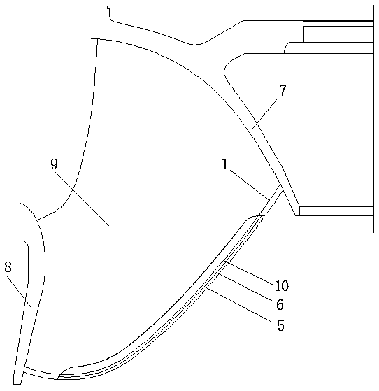
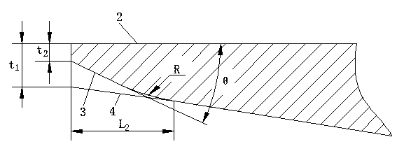
[0035]a. Cut out the airfoil of the blade and determine the repair area of ​​the blade outlet side 1. The blade outlet side 1 includes an integrally formed upper section, a middle section and a lower section, and the length of the upper section and the lower section are both L 1 , L 1 It is 3% of the nominal diameter of the runner, the middle section is the trimmed area, the upper and lower sections are the non-profiled area, the transition between the profiled area and the non-profiled area is smooth, and the thickness of the outlet edge of the blade before the trimming is t 1 ;

[0036] b. Thickness of blade outlet edge after trimming is t 2 , the thickness of the outlet edge of the blade after modification is the thickness of the outlet edge of the blade before modification t 1 0.4 times of 0.4; the angle θ between the straight line segment in the blade fron...

Embodiment 2

[0043] A method for modifying the outlet edge of a Francis turbine runner blade, comprising the following steps:

[0044] a. Cut out the airfoil of the blade and determine the repair area of ​​the blade outlet side 1. The blade outlet side 1 includes an integrally formed upper section, a middle section and a lower section, and the length of the upper section and the lower section are both L 1 , L 1 It is 3.5% of the nominal diameter of the runner, the middle section is the trimmed area, the upper and lower sections are the non-modified area, the transition between the trimmed area and the non-modified area is smooth, and the thickness of the outlet edge of the blade before the trimming is t 1 ;

[0045] b. Thickness of blade outlet edge after trimming is t 2 , the thickness of the outlet edge of the blade after modification is the thickness of the outlet edge of the blade before modification t 1 0.45 times of 0.45 times; the angle θ between the straight line segment in the ...

Embodiment 3

[0053] A method for modifying the outlet edge of a Francis turbine runner blade, comprising the following steps:

[0054] a. Cut out the airfoil of the blade and determine the repair area of ​​the blade outlet side 1. The blade outlet side 1 includes an integrally formed upper section, a middle section and a lower section, and the length of the upper section and the lower section are both L 1 , L 1 It is 4% of the nominal diameter of the runner. The middle section is the trimmed area, and the upper and lower sections are non-profiled areas. There is a smooth transition between the trimmed area and the non-profiled area. The thickness of the outlet edge of the blade before the trimming is t 1 ;

[0055] b. Thickness of blade outlet edge after trimming is t 2 , the thickness of the outlet edge of the blade after modification is the thickness of the outlet edge of the blade before modification t 1 0.5 times of ; the angle θ between the straight line segment in the blade front ...


PUM


Abstract

Disclosed is a trimming method for a blade outlet edge (1) of a mixed-flow water turbine runner. The method comprises the steps of: cutting out a blade wing profile, and determining a blade outlet edge (1) trimming area; enabling an after-trimming blade back molded line (3) and a pre-trimming blade back molded line (4) to be in circular arc transition, wherein the radius R of the circular arc is 4-7 times of the thickness t1 of the blade outlet edge before trimming; determining the final geometric dimension of trimming of the blade outlet edge (1); determining the sizes of a child-mother sample plate (11, 12) and a circular arc sample plate (13) of the back of the blade, and integrally machining the child-mother sample plate and the circular arc sample plate of the back of the blade; marking off on the blade outlet edge (1), and determining the final position of a back pressure edge (6) of the outlet of the blade after trimming; adjusting the angle of the blade outlet edge (1) until the angle meets the size of the child-mother sample plate (11, 12); and grinding the circular arc of the back of the blade until the circular arc meets the size of the circular arc sample plate (13) of the back of the blade. The method can prevent or eliminate water turbine hissing and blade cracks generated by blade hydraulic power elastic resonance induced by Karman Vortex of a runner outlet, and improves the structural integrity of the mixed-flow water turbine runner and the operation safety of the water turbine.

Description

technical field [0001] The invention relates to the field of water turbines, in particular to a method for modifying the outlet edge of runner blades of a Francis water turbine. Background technique [0002] Among all the flow-induced vibration problems of Francis turbines, the resonance induced by the Karman vortex street at the outlet of the runner blades is a very destructive hydroelastic vibration. Once this kind of resonance occurs, there will be howling noise when the turbine is running, and it will cause large area cracks in the runner blades in a short time. The resonance induced by the Karman vortex street at the outlet of the Francis turbine runner blades usually appears in the operating area of ​​the runner with high flow velocity, that is, the high load operating area of ​​the Francis turbine. In addition, the frequency of howling is high, and the frequency of howling increases with the increase of turbine load. Therefore, in actual engineering, it is not diffi...

Claims


Application Information

Patent Timeline
Patent Type & Authority Patents(China)
IPC IPC(8): F03B3/12F03B3/02F03B11/04B24B19/14
CPCB24B19/14F03B3/02F03B3/121F03B11/04Y02E10/20Y02P70/10
Inventor 石清华龚莉李国元
Owner DONGFANG ELECTRIC MACHINERY
Why Eureka
Try Eureka