Light-emitting device and preparation method thereof

A light-emitting device and light-emitting layer technology, applied in the optical field, can solve problems such as cracking, peeling and falling off, increased difficulty of coating process, low porosity, etc., achieve simple and convenient processing, avoid sintering and detachment phenomenon, and facilitate coating effects

Active Publication Date: 2018-10-23
APPOTRONICS CORP LTD
View PDF9 Cites 2 Cited by
  • Summary
  • Abstract
  • Description
  • Claims
  • Application Information

AI Technical Summary

Problems solved by technology

[0007] Aiming at the above deficiencies in the prior art, the present invention proposes a light-emitting device with a gradient concentration. By controlling the mass fraction and distribution of the fluorescent material in each layer, a low-concentration layer is designed. The "relief" structure of the coating interface caused by the different hardness of the bonding medium increases the difficulty of the coating process; on the other hand, the porosity between the interfaces of each concentration layer of this structure is low, and there is no excessive concentration difference. Avoid quality problems such as cracking, peeling and falling off caused by the large difference in expansion coefficient during the sintering process;

Method used


Image

  • Light-emitting device and preparation method thereof
  • Light-emitting device and preparation method thereof
  • Light-emitting device and preparation method thereof

Examples


Embodiment 1

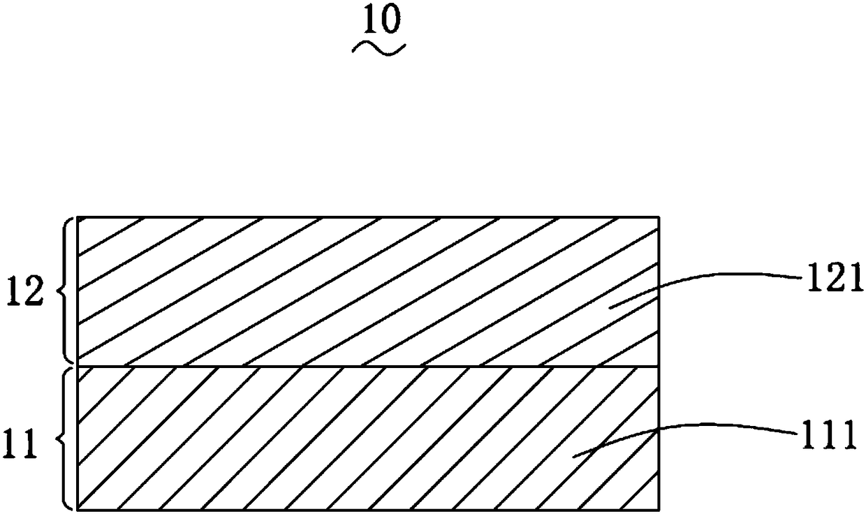
[0036] Please refer to figure 1 , the present invention provides a light-emitting device 10, the components of which include fluorescent powder and a binder for bonding.

[0037] In this embodiment, the phosphor is commercially available Y 3 Al 5 o 12 : Ce 3+ Phosphor powder; the binder is glass powder or alumina powder or Y 3 Al 5 o 12 Powder, mainly plays the role of bonding several other components. The hardness of the binder is different from that of the fluorescent powder, for example: the Mohs hardness of the glass powder is 5.5-6, the Mohs hardness of the phosphor powder is 8-8.5, and the aluminum oxide powder Mohs hardness is 9. The light-emitting device of the present invention is designed with a low-concentration layer, and the coating film can be polished on the layer. Because the hardness of the phosphor powder and the bonding medium are different, the wear state will be different when the high-concentration layer is polished, forming "relief". The low-co...

Embodiment 2

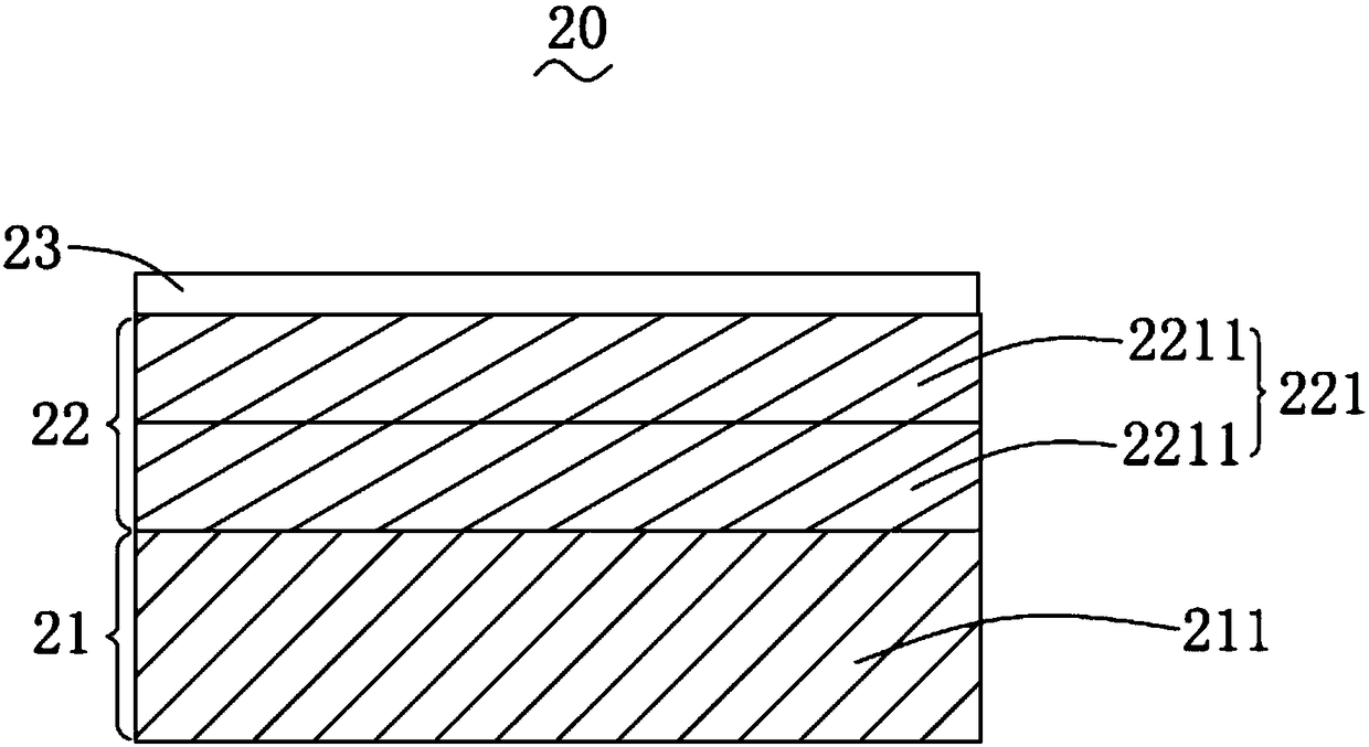
[0046] Please refer to figure 2 , the present invention provides a light-emitting device 20, the components of which include fluorescent powder and a binder for bonding.

[0047] In this embodiment, the phosphor is commercially available Y 3 Al 5 o 12 : Ce 3+ Phosphor powder; the binder is glass powder or alumina powder or Y 3 Al 5 o 12 Powder, mainly plays the role of bonding several other components. The hardness of the binder is different from that of the fluorescent powder, for example: the Mohs hardness of the glass powder is 5.5-6, the Mohs hardness of the phosphor powder is 8-8.5, and the aluminum oxide powder Mohs hardness is 9.

[0048] The light-emitting device 20 is designed to be pressed and sintered in a gradient-differentiated concentration ratio method, and includes an integrated sintered body of a light-emitting layer 21 and a functional layer 22 laminated on the light-emitting layer 21 .

[0049] The light-emitting layer 21 includes a first light-emi...

Embodiment 3

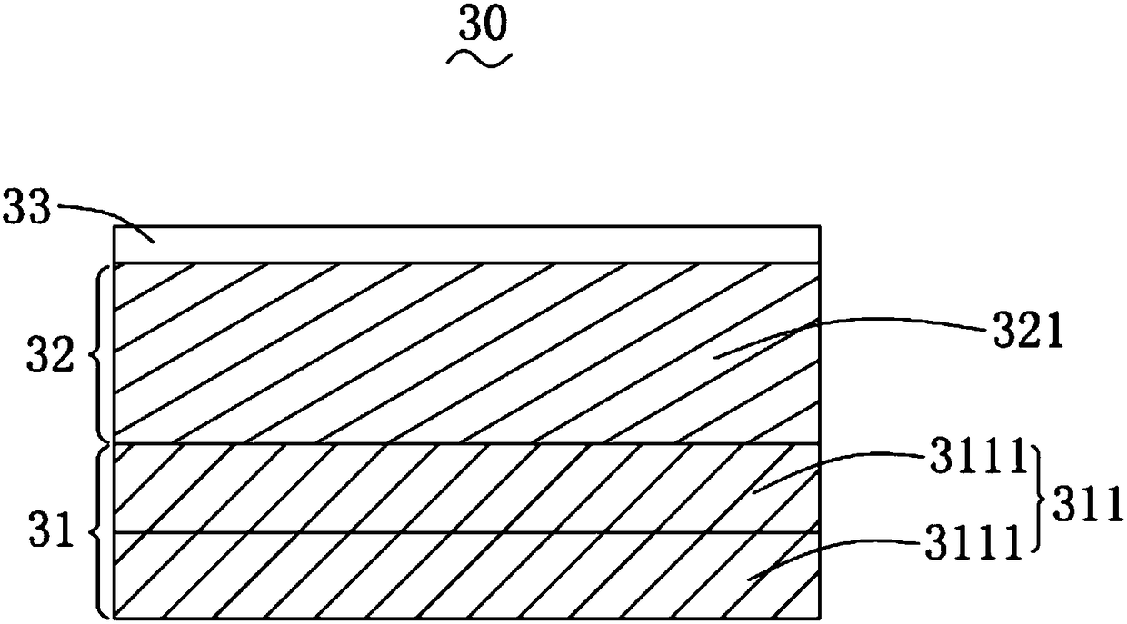
[0059] Please refer to image 3 , the present invention provides a light-emitting device 30, the components of which include fluorescent powder and a binder for bonding.

[0060] In this embodiment, the phosphor is commercially available Y 3 Al 5 o 12 : Ce 3+ Phosphor powder; the binder is glass powder or alumina powder or Y 3 Al 5 o 12 Powder, mainly plays the role of bonding several other components. The hardness of the binder is different from that of the fluorescent powder, for example: the Mohs hardness of the glass powder is 5.5-6, the Mohs hardness of the phosphor powder is 8-8.5, and the aluminum oxide powder Mohs hardness is 9. The light-emitting device of the present invention is designed with gradient concentration to form a low-concentration layer, and the coating film is polished on the layer. Because the hardness of the phosphor powder and the bonding medium are different, the wear state will be different when the high-concentration layer is polished, fo...


PUM

PropertyMeasurementUnit
thicknessaaaaaaaaaa
thicknessaaaaaaaaaa
thicknessaaaaaaaaaa

Abstract

The present invention provides a light-emitting device and a preparation method thereof. The components of the light-emitting device comprise fluorescent powder and a binder for bonding. The light-emitting device is an integrated sintered body comprising a light-emitting layer and a functional layer laminated on the light-emitting layer; the light-emitting layer includes a first light-emitting layer; the mass fraction of the fluorescent powder in the first light-emitting layer ranges from 50% to 99%; the thickness of the first light-emitting layer ranges from 150 to 200 microns; the functionallayer includes a first functional layer; the mass fraction of the fluorescent powder in the first functional layer ranges from 5% to 50%; the thickness of the first functional layer ranges from 5 to50 microns; a continuous dense transition layer is arranged between the light-emitting layer and the functional layer; and the Moh's hardness of the fluorescent powder is different from the Moh's hardness of the binder. With the light-emitting device and the preparation method thereof of the invention adopted, the problem of difficulty in film plating caused by the inconsistency of the polishing flatness of a multiphase material light-emitting device can be solved; the inter-layer porosity of the light-emitting device is low, so that the phenomenon of sintering detachment can be avoided; and therefore, the reliability of the light-emitting device can be improved, and the yield of finished products can be improved.

Description

technical field [0001] The invention belongs to the field of optical technology, and in particular relates to a light-emitting device and a preparation method thereof. Background technique [0002] In recent years, with the rapid development of high-quality green lighting and high-end display technology, the application of high-energy-density excitation methods such as laser diodes (laserdiodes, LD) and high-power white LEDs has put forward new challenges for the radiation resistance and structural stability of fluorescent materials. Due to higher requirements, light wavelength conversion materials with phosphor powder and silica gel as main raw materials have been widely used in laser light sources and LED (Light Emitting Diode, Light Emitting Diode) light sources. As people's requirements for brightness continue to increase, the optical power of the excitation light is also getting higher and higher. This kind of light wavelength conversion sheet made of phosphor powder an...

Claims


Application Information

Patent Timeline
Patent Type & Authority Applications(China)
IPC IPC(8): H01L33/50H01L33/26
CPCH01L33/26H01L33/501H01L33/502H01L33/507H01L2933/0041H01L33/50
Inventor 陈雨叁李乾徐梦梦许颜正
Owner APPOTRONICS CORP LTD
Why Eureka
Try Eureka