A micro-chamber microfluidic system for microbial growth image detection

A microfluidic system and image detection technology, applied in the field of microbial detection, can solve the problems of limiting microbial movement, microbial contact with culture medium, unfavorable microbial growth, microbial growth and movement restrictions, etc., to achieve true and reliable data, accurate measurement, The effect of less sample consumption

Active Publication Date: 2018-11-06
JINAN UNIVERSITY
View PDF4 Cites 3 Cited by
  • Summary
  • Abstract
  • Description
  • Claims
  • Application Information

AI Technical Summary

Problems solved by technology

[0006] Although microfluidic chips have made some progress in the field of bacteria and cells, there are still many technical defects in the cultivation of microorganisms. For example, the channel culture mode is often used, and the cultivation of a single channel will limit the growth and movement of microorganisms; In addition, the double-layer restricted culture mode is often used, that is, the bottom layer

Method used


Image

  • A micro-chamber microfluidic system for microbial growth image detection
  • A micro-chamber microfluidic system for microbial growth image detection
  • A micro-chamber microfluidic system for microbial growth image detection

Examples


Example Embodiment

[0062] Example 1

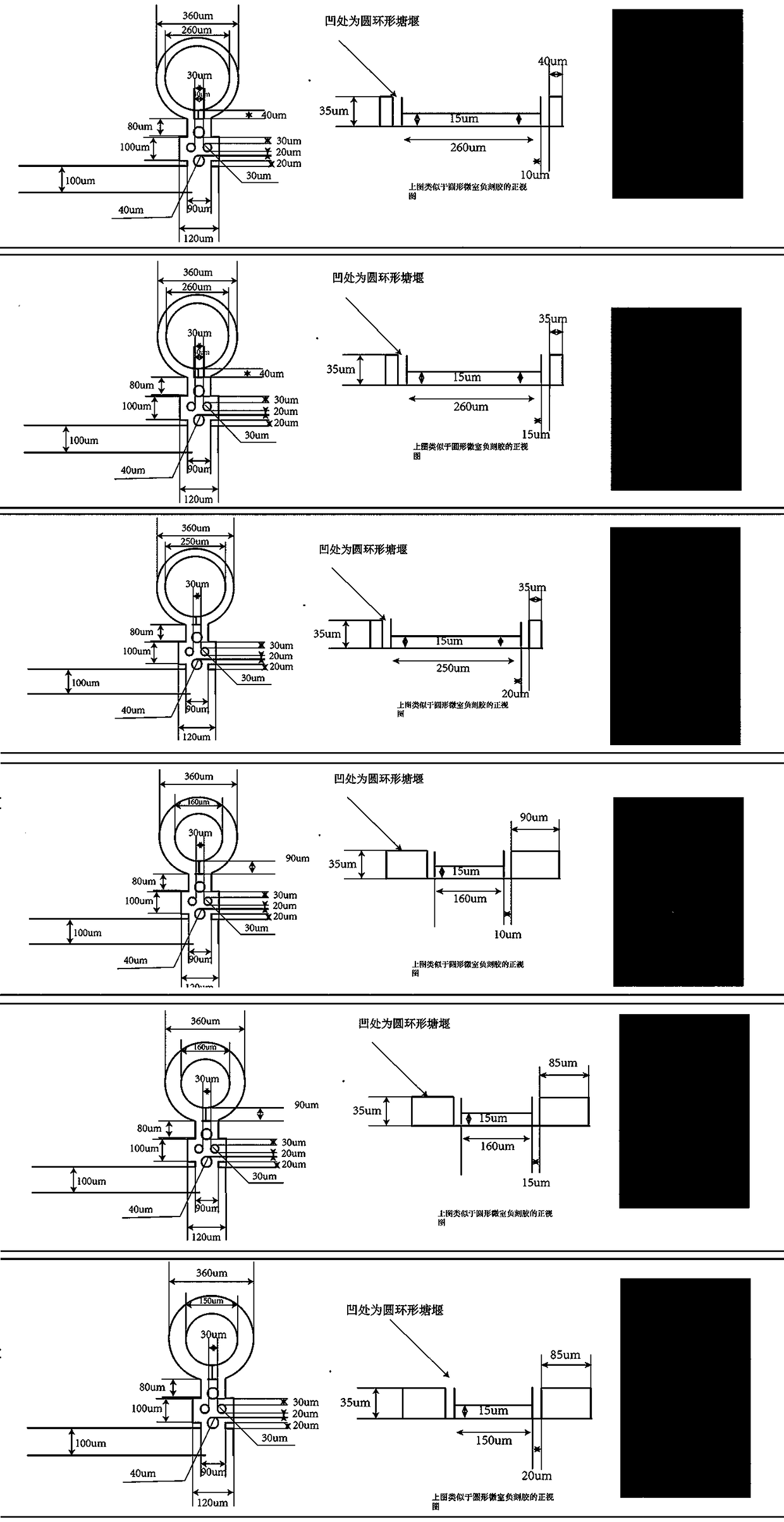
[0063] Such as Figure 1~4 As shown, this embodiment discloses a micro-chamber microfluidic chip for real-time cultivation and observation of microorganisms. The microfluidic chip includes a chip body and a PDMS film integrally molded therewith. The chip body includes four A microfluidic channel, the microfluidic channel is composed of a liquid inlet 1, a main channel 2 and a liquid outlet 3 that are connected in sequence; the middle part of the main channel 1 is the micro-chamber area of ​​the microfluidic chip, and the main channel The middle section of 1 is in the shape of a broken line, and the angle between each other is 90°. The main channel of the broken line extends outwards in the direction of the liquid flow at the corners to form an annular channel and a micro-chamber with a cofferdam structure. 4 A T-shaped corner 5 is provided at one end close to the main channel; a micro-pillar 6 is provided on the channel between the micro chamber 4 and the main...

Example Embodiment

[0071] Example 2

[0072] Such as Image 6 As shown, this embodiment discloses a micro-chamber micro-fluidic control system for microbial growth image detection, including a microscope, a constant-current injection pump, a syringe, a constant-temperature stage, the micro-chamber micro-fluidic chip described in Example 1, and a collector , CMOS video detection components, video recorders, mobile hard drives and displays; the constant temperature stage is placed on the microscope stage; the micro-chamber microfluidic chip is placed on the constant temperature stage to provide a constant culture for the chip The temperature and size are suitable for the microscope and the chip; the CMOS video detection component is fixed on the top of the microscope by connection, and the CMOS video detection component is used to measure the morphology of bacteria in each microchamber in the microchamber microfluidic chip. Change; the liquid inlet of the microchamber microfluidic chip is connected w...


PUM


Abstract

A micro-chamber microfluidic system for microbial growth image detection is disclosed. The system includes a microscope, a constant current syringe pump, a syringe, a constant-temperature stage, a micro-chamber microfluidic chip, a collector and a CMOS video detection component. The constant-temperature stage is disposed on a microscope stage. The micro-chamber microfluidic chip is arranged on theconstant-temperature stage. A micro-chamber structure having an independent design can be used for real-time microbial culture. The CMOS video detection component is connected and fixed above the microscope, and is used for measuring morphological changes of bacteria in each micro-chamber in the micro-chamber microfluidic chip. The CMOS video detection component also includes a computation unit,and the computation unit is used for acquiring clear gray level image information of microbes based on a linear spatial filtering implementing principle and a corresponding segmentation equation and coefficients. The system effectively overcomes a technical defect that traditional microbial image detection methods are time-consuming, labor-consuming, expensive, single in function, and incapable ofacquiring long-time real-time real microbial growth image information, and has a great application prospect.

Description

technical field [0001] The invention belongs to the technical field of microorganism detection, and more specifically relates to a microchamber microfluidic system for detecting microorganism growth images. Background technique [0002] The cultivation of microorganisms is the basic technology in the fields of life science and medical research, as well as industrial fermentation and food testing. However, in the current field of bacterial culture and detection, only the growth curve of bacteria can be obtained as a detection index, that is, the use of turbidity detection devices, such as Spectrophotometer, microplate reader, etc. to obtain the change curve of bacterial cell density and number. However, with the development of science, technology and economy, this detection technology can no longer meet the requirements of today's scientific research and the detection field of food fermentation industry. Therefore, there is an urgent need for a detection device with high thr...

Claims


Application Information

Patent Timeline
IPC IPC(8): C12M1/34C12M1/00
CPCC12M23/16C12M41/36
Inventor 孙雪松杜高飞
Owner JINAN UNIVERSITY
Why Eureka
Try Eureka