Ion bombardment preparation method for self-organizing nano-structure with saw-toothed outline
A nanostructure and ion bombardment technology, applied in nanotechnology, microstructure technology, microstructure devices, etc., can solve the problem of no blazed grating structure, and achieve the effect of widening the control range, low cost and low cost
- Summary
- Abstract
- Description
- Claims
- Application Information
AI Technical Summary
Problems solved by technology
Method used
Image
Examples
Embodiment 1
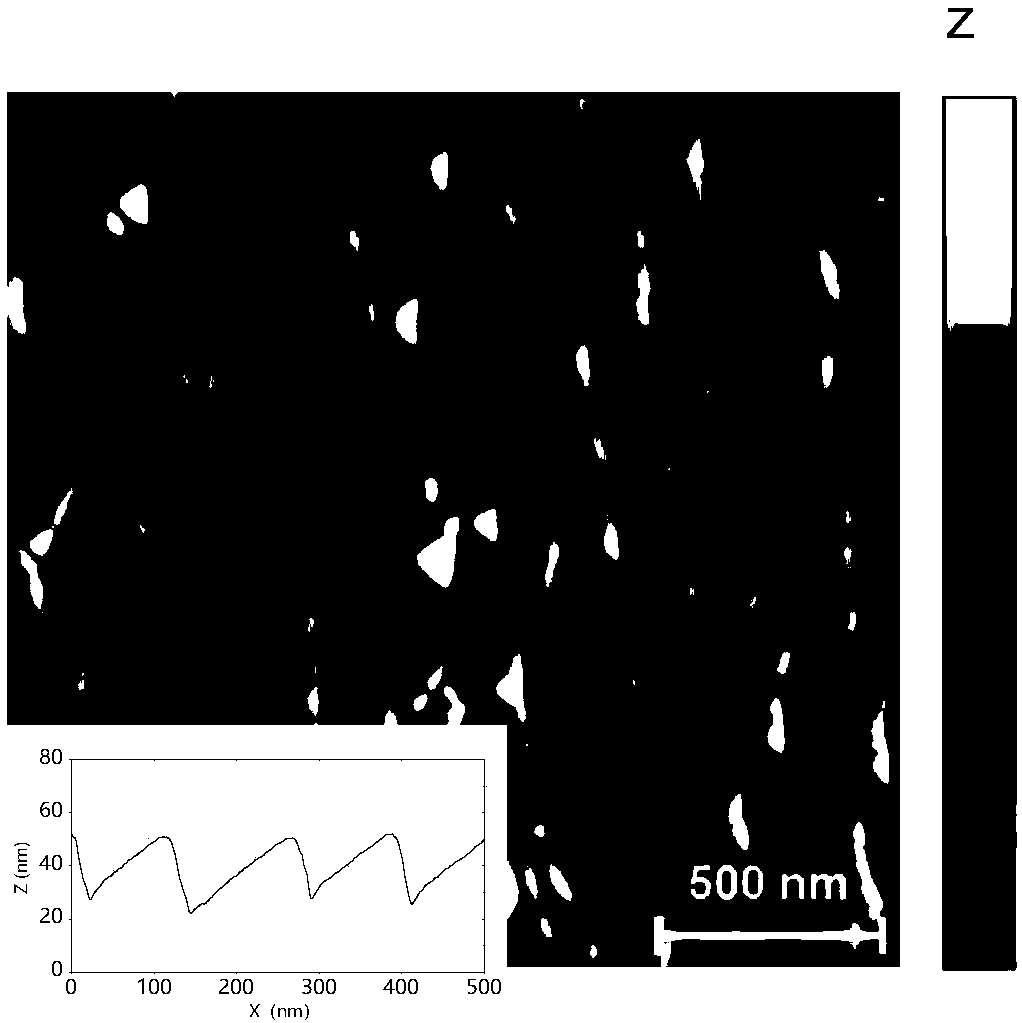
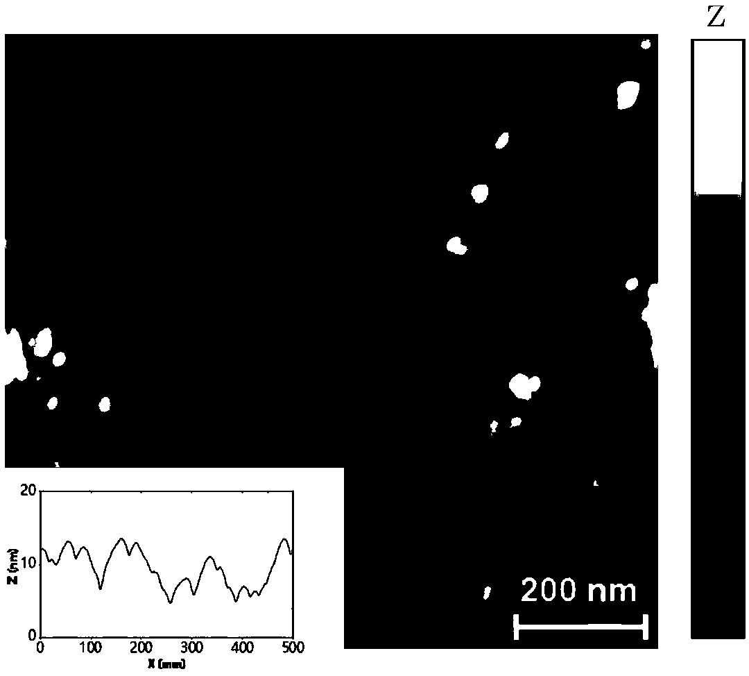
[0052] Example 1, comparing the surface morphology produced by simple ion bombardment without introducing impurities and ion bombardment introducing impurities:
[0053] The fused silica sample (20mm×20mm×2mm) to be processed was ultrasonically soaked in acetone or soaked in SPM solution (concentrated sulfuric acid:hydrogen peroxide=2:1) for 30 minutes. After taking it out, rinse it with 80°C deionized water for 5 minutes. Finally put it into an oven at 110°C and bake for 30 minutes. The surface of the high-purity molybdenum metal target to be bombarded (purity 99.99%, 10mm×20mm×1mm) was polished to a mirror-like state with 7000-grit sandpaper, and then ultrasonically cleaned with acetone.
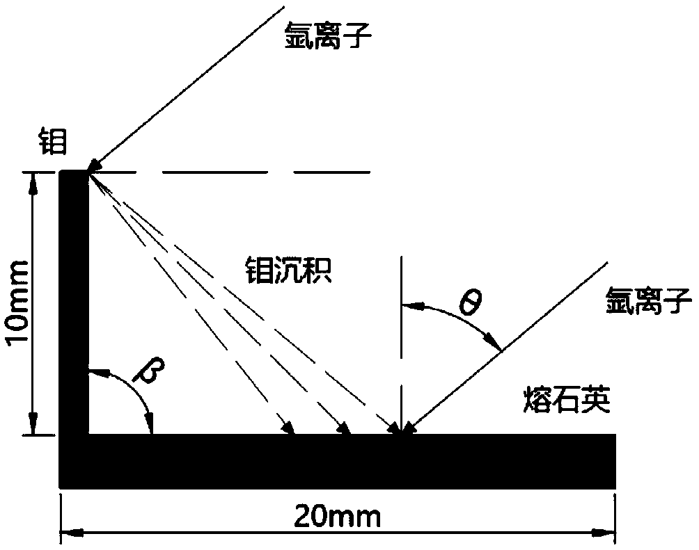
[0054] Complete the pretreatment of high-purity molybdenum metal target according to figure 1 The geometric relationship shown is fixed on the fused silica sample, and then the fused silica sample is fixed on the sample stage of the ion bombardment equipment with vacuum silicone grease...
Embodiment 2
[0059] Implementation example 2 shows how to regulate the structure facet angle by adjusting the ion beam incident angle θ:
[0060] The pretreatment process is consistent with the implementation example 1, but the fixed ion beam energy is 500eV, and the beam current density is 300μA cm -2 , The ion bombardment time is 30min, and the ion bombardment experiment is carried out on the fused silica samples to be processed under different ion beam incident angles θ, so as to obtain the sawtooth profile self-organized nanostructure with different facet angles; Use AFM to detect the surface morphology of the fused silica sample at the position of , and obtain AFM data, such as Figure 4 shown. Figure 5 is a schematic diagram of the facet angle of the cross-sectional view of the AFM image of the sample surface in the incident plane of the ion beam, where α - is the facet angle of the surface profile facing the direction of the ion beam, α + is the facet angle of the surface profil...
Embodiment 3
[0062] Example 3 is implemented, showing how to adjust the pattern period and amplitude by adjusting the ion bombardment time:
[0063] Pretreatment process is consistent with embodiment 1, but fixed ion beam incident angle 50 ° (as Figure 7 shown), ion beam energy 500eV, beam current density 300μA cm -2 , the ion bombardment experiments were carried out under different ion bombardment time t (ion beam flux) to obtain sawtooth profiles with different amplitudes and periods; after the ion bombardment experiments were completed, the AFM was used to detect the fused silica sample at a position 5mm away from the impurity target. Surface topography, get AFM data, such as Figure 8 shown. Figure 9 , 10 It is shown that the roughness and period of the pattern increase with the increase of ion bombardment time, and the facet angle is stable after 30 minutes of bombardment, so after the facet is stabilized, the amplitude and period of the sawtooth profile can be controlled by adju...
PUM
 Abstract
Description
Claims
Application Information
 - R&D
- Intellectual Property
- Life Sciences
- Materials
- Tech Scout
- Unparalleled Data Quality
- Higher Quality Content
- 60% Fewer Hallucinations
Browse by: Latest US Patents, China's latest patents, Technical Efficacy Thesaurus, Application Domain, Technology Topic, Popular Technical Reports.
© 2025 PatSnap. All rights reserved.Legal|Privacy policy|Modern Slavery Act Transparency Statement|Sitemap|About US| Contact US: help@patsnap.com


