
Depolarization measurement and compensation device based on liquid crystal light modulator

A technology of optical modulator and compensation device, which is applied in the direction of lasers, laser components, phonon exciters, etc., can solve the problems of uneven distribution of polarization state of outgoing laser, uneven stress distribution, loss of light intensity in spot area, etc., to achieve Achieve multiplexing, spatial multiplexing, and good beam quality

Inactive Publication Date: 2018-11-06
SHANGHAI INST OF OPTICS & FINE MECHANICS CHINESE ACAD OF SCI
View PDF17 Cites 2 Cited by
  • Summary
  • Abstract
  • Description
  • Claims
  • Application Information

AI Technical Summary

Problems solved by technology

Due to the birefringence effect, the phase delay of the o-light and e-light of the laser will be inconsistent, and the laser polarization will rotate after passing through the laser medium, that is, the uneven stress distribution will cause the polarization state distribution of the outgoing laser to be uneven. Regional light intensity loss, resulting in depolarization loss
[0003] In the laser amplification system, polarization elements such as electro-optic switches and wave plates are often used. The power-on voltage of the electro-optic switch is not enough or the voltage felt by different parts of the crystal is inconsistent, the rotation angle of the wave plate is deviated or the polarization rotation is not uniform, which will lead to the laser spot diameter. Inhomogeneity of the internal polarization state, which in turn leads to depolarization loss

Method used


Image

  • Depolarization measurement and compensation device based on liquid crystal light modulator

Examples


Embodiment Construction

[0021] The following is a further detailed description with reference to the drawings and examples.

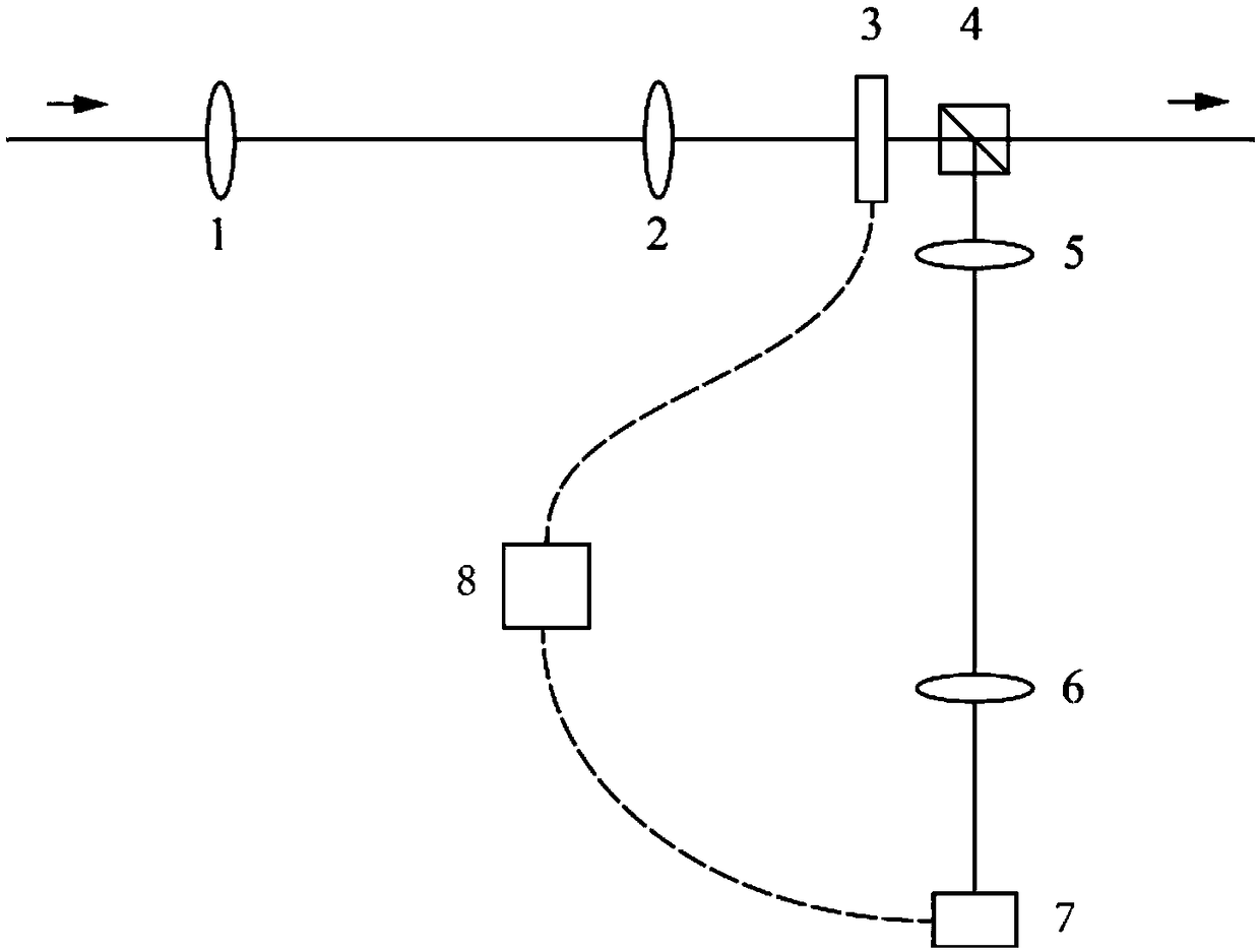
[0022] figure 1 It is a structural schematic diagram of the depolarization measurement and compensation device based on the liquid crystal light modulator of the present invention. Such as figure 1 As shown, a depolarization measurement and compensation device based on a liquid crystal light modulator includes a first lens with a focal length of 20cm, a second lens with a focal length of 20cm, and a light-addressable liquid crystal with a diameter of 2.5cm×2.5cm. Spatial light modulator 3, polarization beam splitting prism 4 with a size of 25.4mm×25.4mm×25.4mm, a third lens 5 with a focal length of 20cm, a fourth lens 6 with a focal length of 20cm, a high-precision CCD7 and a serial port communication function Control computer 8.

[0023] When the laser is incident, the image plane of the parallel laser is set 20cm to the left of the first lens 1, the distance between the first ...


PUM


Abstract

The invention provides a depolarization measurement and compensation device based on liquid crystal light modulator. The depolarization measurement and compensation device based on the liquid crystallight modulator comprises a first lens, a second lens, a light addressing liquid crystal spatial light modulator, a polarization splitter prism, a third lens, a fourth lens, a CCD and a control computer. The depolarization measurement and compensation device based on the liquid crystal light modulator can be used in various laser amplifiers with laser energy flux less than 300 mJ / cm<2> to compensate the laser depolarization effect caused by thermal effect and unsatisfactory polarization elements. The invention is completely based on image transfer design, and can conveniently measure and compensate the depolarization effect of the laser in real time, therefore, the complex steps of dismantling optical devices in the process of conversion measurement and compensation depolarization are avoided. The depolarization measurement and compensation device based on the liquid crystal light modulator has simple structure, can compensate for any form of depolarization, avoid the complex system ofcompensating comprehensive depolarization form, and reduce the complexity of the laser system.

Description

Technical field [0001] The invention relates to the field of laser amplifier depolarization compensation, in particular to a depolarization measurement and compensation device based on a liquid crystal light modulator. Background technique [0002] In the field of laser amplifiers, the heat generation of the laser medium itself will cause the temperature gradient distribution in the body. Due to the existence of the elasto-optical effect, the temperature gradient effect will be transformed into an uneven distribution of stress. The uneven stress distribution often results in the rotation of the laser stress coordinate axis in the plane perpendicular to the laser transmission direction, and the refractive index of the two stress principal axes are not consistent, that is, the stress-induced birefringence effect. Due to the birefringence effect, the phase retardation of the o-ray and e-ray of the laser is inconsistent. After passing through the laser medium, it appears as laser pol...

Claims


Application Information

Patent Timeline
Patent Type & Authority Applications(China)
IPC IPC(8): H01S3/10
CPCH01S3/10061
Inventor 李学春黄庭瑞黄文发黄大杰
Owner SHANGHAI INST OF OPTICS & FINE MECHANICS CHINESE ACAD OF SCI
Learn More