Centralized and real-time processing system for laboratory waste
A real-time treatment and waste technology, which is used in neutralizing water/sewage treatment, solid waste removal, heating water/sewage treatment, etc. It can solve the problem of high treatment costs for professional companies, untimely waste treatment, and cumbersome treatment processes. problems, to achieve the effect of increasing the rate of physical and chemical reaction, prolonging the service life, and increasing the wall area
- Summary
- Abstract
- Description
- Claims
- Application Information
AI Technical Summary
Problems solved by technology
Method used
Image
Examples
Embodiment 1
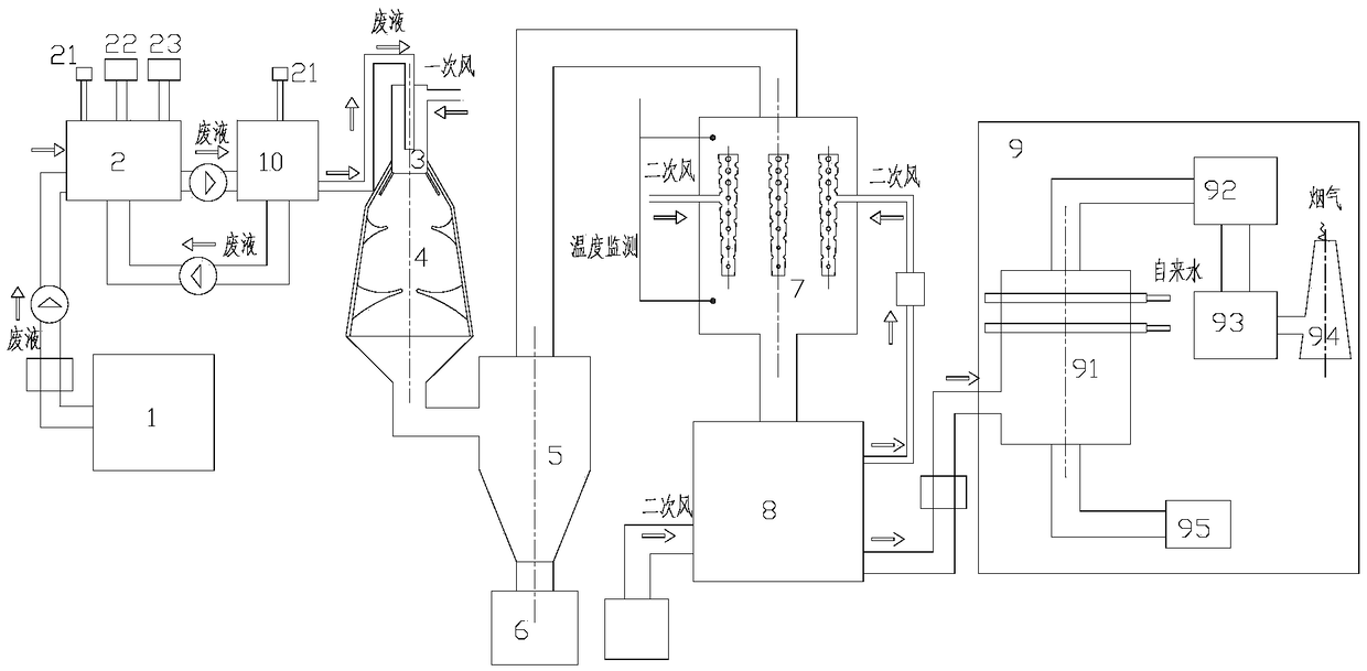
[0066] The invention provides a centralized and real-time processing system for laboratory waste, the structure of which is as follows: figure 1 As shown, it includes: waste liquid storage tank 1, waste liquid neutralization device 2, waste liquid buffer device 10, premixing device 3, primary reaction device 4, particle collection device 5, particle storage tank 6, secondary reaction device 7 , Secondary air supply device 8, purification device 9.
[0067] The function and structure of each device are as follows:
[0068] Waste liquid storage tank 1, used for storing the collected waste liquid;
[0069] The waste liquid neutralization device 2 is used to neutralize the waste liquid to form waste liquid to be treated. It is provided with a pH meter 21, an acid adding unit 22 and an alkali adding unit 23. Wherein the pH meter 21 is used to measure the pH value of the waste liquid; the acid adding unit 22 is used to provide the acid solution and joins the acid solution in the ...
Embodiment 2
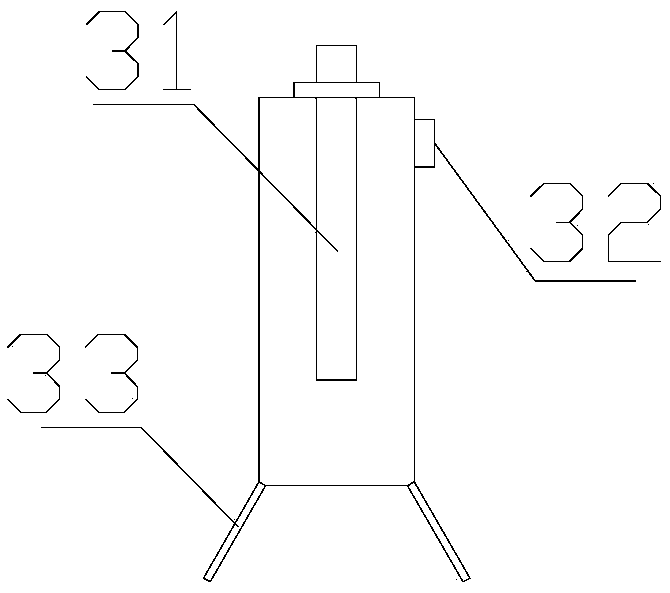
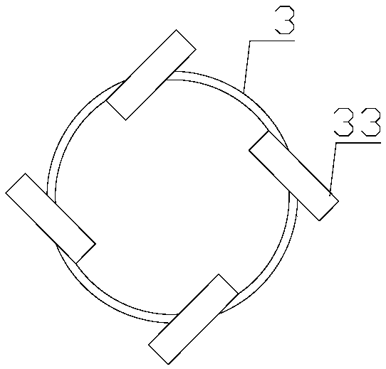
[0100] Embodiment 2 is the same as Embodiment 1, and also includes a waste liquid storage tank 1, a waste liquid neutralization device 2, a pH meter 21, an alkali addition unit 22, an alkali addition unit 23 waste liquid buffer device 10, a premixing device 3, and a mist Catifier 31, primary tuyere 32, injector 33, primary reaction device 4, particle collection device 5, particle storage tank 6, secondary reaction device 7, secondary air supply device 8, purification device 9, spray tower 91, Activated carbon adsorption device 92, dust removal equipment 93, chimney 94 and liquid collection device 95. The difference is the structure of the primary mixing plate 41 and the secondary mixing plate 42 in the primary reaction device 4 in the second embodiment.
[0101] The structure of the primary mixing plate 41 in the second embodiment is as follows Figure 4-4 , the structure of the secondary mixing plate 42 is as follows Figure 4-5 . combine Pic 4-1 and Figure 4-4 , there...
Embodiment 3
[0108] The difference between Embodiment 3 and the above-mentioned Embodiment 1 and Embodiment 2 is that the primary reaction device 4 has an inverted pyramid structure as a whole, such as Figure 6 shown. In the third embodiment, the primary mixing plate 41 and the secondary mixing plate 42 are also provided, and the structure of the two-stage mixing plate may be the same as that of the primary mixing plate 41 and the secondary mixing plate 42 in the first and second embodiments. The rest of the components in the third embodiment are the same as those in the first and second embodiments, and will not be described in detail here.
PUM
 Abstract
Description
Claims
Application Information
 - R&D
- Intellectual Property
- Life Sciences
- Materials
- Tech Scout
- Unparalleled Data Quality
- Higher Quality Content
- 60% Fewer Hallucinations
Browse by: Latest US Patents, China's latest patents, Technical Efficacy Thesaurus, Application Domain, Technology Topic, Popular Technical Reports.
© 2025 PatSnap. All rights reserved.Legal|Privacy policy|Modern Slavery Act Transparency Statement|Sitemap|About US| Contact US: help@patsnap.com


