Boiler continuous blowdown wastewater waste heat utilization system and method

A continuous row, boiler technology, applied in steam boilers, preheating, supplementary water supply, etc., can solve the problems of high energy consumption and high investment, and achieve the effects of long service life, improved thermal efficiency, and low maintenance costs

Active Publication Date: 2018-11-13
浙江巨化热电有限公司
View PDF7 Cites 2 Cited by
  • Summary
  • Abstract
  • Description
  • Claims
  • Application Information

AI Technical Summary

Problems solved by technology

[0005] In order to solve the problems of high investment and high energy consumption in eliminating colored plume at the present stage, the purpose of the present invention is to provide a boiler continuous waste water waste heat utilization system and its method with simple structure, energy saving and environmental protection, and efficient elimination of chimney white smoke

Method used


Image

  • Boiler continuous blowdown wastewater waste heat utilization system and method
  • Boiler continuous blowdown wastewater waste heat utilization system and method
  • Boiler continuous blowdown wastewater waste heat utilization system and method

Examples


Embodiment 1

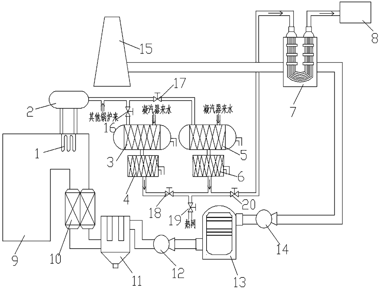
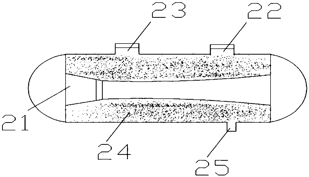
[0030] A boiler waste water waste heat utilization system, comprising a steam drum 2, a boiler 9 (equipped with a high-temperature economizer 1), an air preheater 10, a dry dust collector 11, a first induced draft fan 12, and a wet desulfurization tower 13 , the second induced draft fan 14, the flue gas reheater 7 (a group of heat exchange modules are provided, the heat exchange modules are made of composite material heat exchange tubes obtained by making fluoroplastic PFA film on the surface of the stainless steel base material, and the specifications of the stainless steel heat exchange tubes are φ10×1, fluorine plastic film thickness 0.5mm, external metal tube box sealed, heat exchange tubes arranged in U shape, staggered arrangement), desalted water tank 8 and chimney 15, outlet flue of boiler 9 and air preheater 10 The flue gas inlet of the air preheater 10 is connected to the flue gas inlet of the dry dust collector 11, the flue gas outlet of the dry dust collector 11 is ...

Embodiment 2

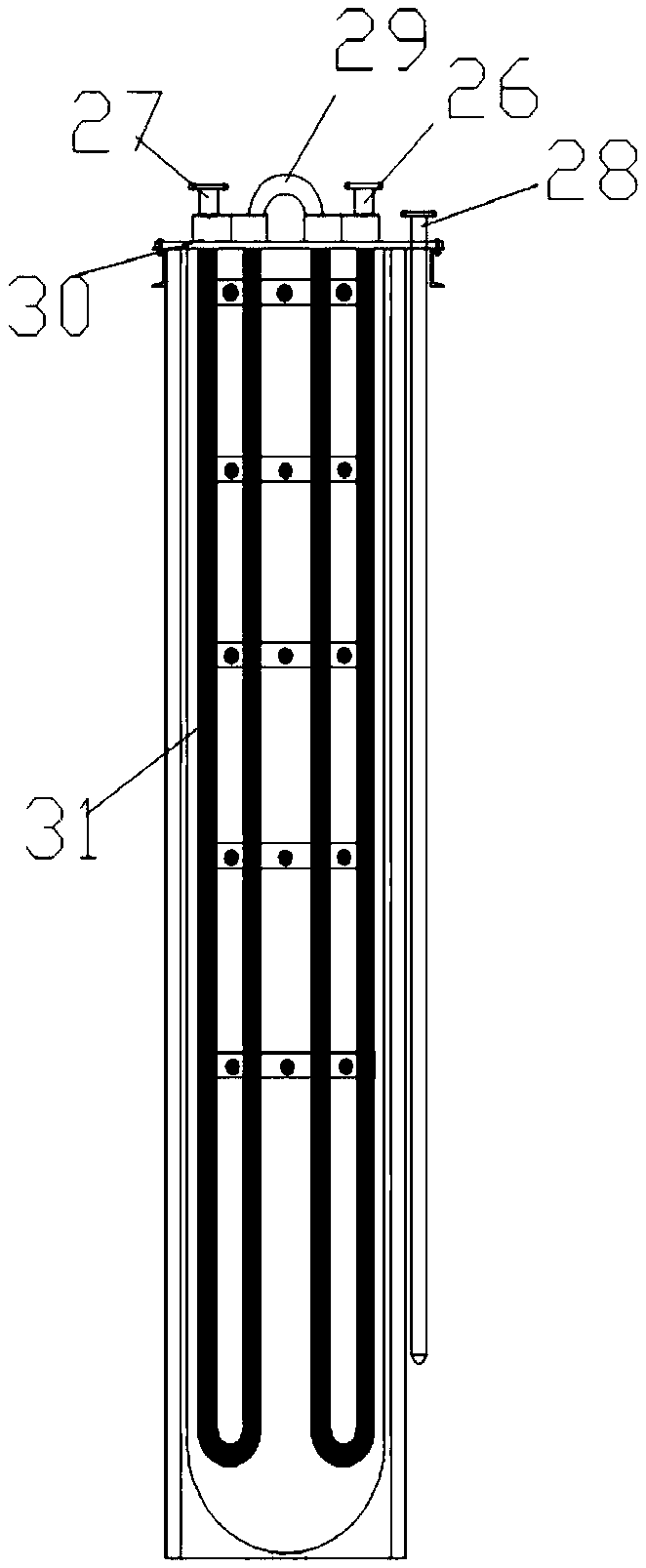
[0034] A boiler waste water waste heat utilization system, comprising a steam drum 2, a boiler 9 (equipped with a high-temperature economizer 1), an air preheater 10, a dry dust collector 11, a first induced draft fan 12, and a wet desulfurization tower 13 , the second induced draft fan 14, the flue gas reheater 7 (two groups of heat exchange modules are provided, the heat exchange modules are made of PTFE heat exchange tubes, and the PTFE heat exchange tube specifications are The heat exchange tubes are connected with the tube plate face plate 29 by welding technology, the tube plate face plate 29 is sealed with the external metal tube box, the heat exchange tubes are arranged in a U-shape, arranged in parallel), the desalinated water tank 8 and the chimney 15, the outlet smoke of the boiler 9 The duct is connected to the flue gas inlet of the air preheater 10, the flue gas outlet of the air preheater 10 is connected to the flue gas inlet of the dry dust collector 11, and the...

Embodiment 3

[0038]A boiler waste water waste heat utilization system, comprising a steam drum 2, a boiler 9 (equipped with a high-temperature economizer 1), an air preheater 10, a dry dust collector 11, a first induced draft fan 12, and a wet desulfurization tower 13 , the second induced draft fan 14, the flue gas reheater 7 (three groups of heat exchange modules are provided, the heat exchange modules are made of PTFE heat exchange tubes, the PTFE heat exchange tube specifications are φ10×1, and the heat exchange tubes adopt welding technology and The tube plate face plate 29 is connected, the tube plate face plate 29 is sealed with the external metal tube box, the heat exchange tubes are arranged in a U shape, and arranged in parallel), the desalted water tank 8 and the chimney 15, the outlet flue of the boiler 9 and the air preheater 10 The flue gas inlet of the air preheater 10 is connected to the flue gas inlet of the dry dust collector 11, the flue gas outlet of the dry dust collecto...


PUM


Abstract

The invention discloses a boiler continuous blowdown wastewater waste heat utilization system. The boiler continuous blowdown wastewater waste heat utilization system comprises a steam pocket, a boiler, an air preheater, a dry type dust collector, a first induced draft fan, a wet desulphurization tower, a second induced draft fan, a gas-gas heater, a desalting water tank and a chimney. A continuous blowdown wastewater waste heat recovery device and a filter cleaning device are arranged between the steam pocket and the gas-gas heater. An inlet of the continuous blowdown wastewater waste heat recovery device is connected with a water outlet of the steam pocket. An outlet of the continuous blowdown wastewater waste heat recovery device is connected with an inlet of the filter cleaning device.An outlet of the filter cleaning device is connected with a water inlet of the gas-gas heater. A water outlet of the gas-gas heater is connected with an inlet of the desalting water tank. The invention further discloses a method for utilizing boiler continuous blowdown wastewater waste heat through the system. The boiler continuous blowdown wastewater waste heat utilization system is simple in structure and achieves the effects that boiler continuous blowdown wastewater waste heat is recovered and used for eliminating gas fume white smoke and recovering water resources.

Description

technical field [0001] The invention belongs to the technical field of energy saving and environmental protection of coal-fired power stations, and in particular relates to a waste heat utilization system and method for boiler continuous waste water. Background technique [0002] At present, most coal-fired power plants in my country have wet desulfurization process and saturated wet flue gas is directly discharged, forming visible wet smoke and rain. With the expansion and acceleration of ultra-low emissions of coal-fired flue gas nationwide, most of the desulfurization devices are not equipped with GGH in order to meet the requirements of ultra-low emission limits. The saturated wet flue gas is discharged from the chimney and mixed with the lower temperature ambient air to cool down. The water vapor is supersaturated and condensed, which refracts and scatters the light, making the smoke and rain appear white or gray "wet smoke and rain" (commonly known as "big white smoke"...

Claims


Application Information

Patent Timeline
Patent Type & Authority Applications(China)
IPC IPC(8): F22B31/08F22D11/06F23J15/08F23J15/02
CPCF22B31/08F22D11/06F23J15/02F23J15/08
Inventor 毛双华林国辉祝云飞
Owner 浙江巨化热电有限公司
Why Eureka
Try Eureka