Linear permanent magnet motor system for high-frequency impact

A technology of permanent magnet motor and high-frequency impact, which is applied in the field of oil-assisted percussion drilling and rock breaking, can solve the problems of being unsuitable for high temperature and high pressure working environment, failing to meet the requirements of working conditions, spring coefficient creep, etc., achieving compact structure, The effect of light weight and high natural frequency

Inactive Publication Date: 2018-11-16
ZHENGZHOU UNIV
View PDF10 Cites 6 Cited by
  • Summary
  • Abstract
  • Description
  • Claims
  • Application Information

AI Technical Summary

Problems solved by technology

Oil drilling is currently using rotary rock breaking. If the reciprocating impact motion can be superimposed on the rotating motion, the efficiency of rock breaking can be greatly improved, and the reciprocating impact linear motion can be realized. For a drill pipe of several kilometers, if the overall impact Movement is impossible, so the impact movement mechanism can only be installed at the downhole drill bit. At the same time, due to the limitation of drilling space, there are strict requirements on the diameter of the mechanism. There is an urgent need for a mechanism that is small in size, capable of high-frequency work, and continuously adjustable in working frequency
Ordinary linear motors work on the ground and cannot withstand high temperature and high pressure environments in structure; conventional reciprocating motors use mechanical spring structures, which have problems such as low natural frequency, easy corrosion damage, and spring coefficient creep. Chinese patent A light DC linear motor is disclosed in 102013783A, but it is not suitable for high temperature and high pressure working environment
Since this technology is a new technology, there is no linear motor system that can meet the requirements of working conditions on the market

Method used


Image

  • Linear permanent magnet motor system for high-frequency impact
  • Linear permanent magnet motor system for high-frequency impact
  • Linear permanent magnet motor system for high-frequency impact

Examples


Embodiment Construction

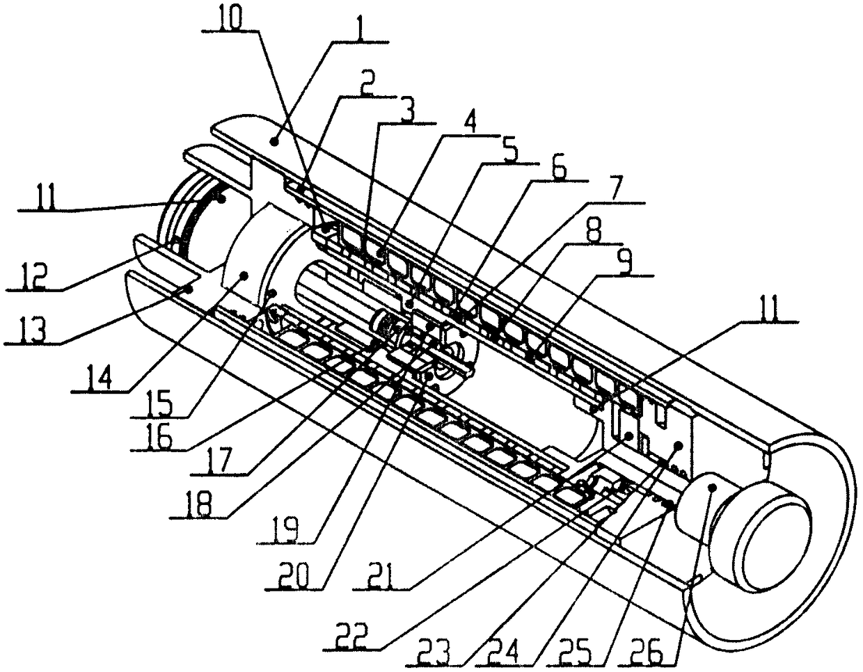
[0015] Such as figure 1As shown, it is mainly composed of stator system, mover system and mechanical system. The stator system includes: outer cylinder 1, inner cylinder 2, stator core 3, winding 4; the mover system includes: mover shaft 5, multiple sets of arranged Permanent magnets, each group of permanent magnets includes N pole 6, magnetic field outward intermediate pole 7, S pole 8, magnetic field inward intermediate pole 9, magnetic steel pressure ring 10, mover upper end 11; mechanical system includes: protector piston 12 , Multifunctional rear support cover 13, return energy storage capsule 14, capsule force cover 15, linear bearing 16, displacement sensor body 17, sensor moving ring 18, moving ring mounting seat 19, moving ring gland 20, anti-collision rubber block 21. Front bearing gland 22, front linear bearing 23, front fixing seat 24, front moving seal 25, impact hammer 26, the upper end of the outer cylinder 1 and the front fixing seat 24 have an interference fit...


PUM


Abstract

The invention relates to a linear permanent magnet motor system for high-frequency impact. The linear permanent magnet motor system for the high-frequency impact mainly comprises a stator system, an active cell system and a mechanical system. The linear permanent magnet motor system for the high-frequency impact is characterized in that the stator system comprises an outer cylinder, an inner cylinder, a stator iron core and windings; the active cell system comprises an active cell shaft, a plurality of sets of permanent magnets arranged by halbach, the permanent magnets comprise N poles, magnetic field outward center poles, S poles, magnetic field inward center poles, magnetic steel press rings and active cell upper end heads; and the mechanical system comprises a protector piston, a seal,a multifunctional rear supporting cover, a return stroke energy storage capsule, a capsule stress cover, a linear bearing, a displacement sensor body, a sensor moving ring, a moving ring mounting seat, a moving ring gland, an anti-collision rubber block, a front linear bearing, a front fixed seat, a front moving seal and a punching hammer. The linear permanent magnet motor system for the high-frequency impact has a wide application range, is mainly used for high-frequency auxiliary impact devices for oil drilling at high temperature and high pressure, and can further be used for occasions requiring high-frequency reciprocating impact movement, such as resonance crushing heads of cement pavements and tunnel rock tunneling auxiliary impact equipment.

Description

technical field [0001] The invention relates to the field of petroleum-assisted percussion drilling and rock breaking. A high-frequency percussion linear permanent magnet motor system invented has high temperature resistance, high pressure, high efficiency, continuously adjustable percussion frequency and motion amplitude, and can be used as an auxiliary tool for underground petroleum drilling. Application occasions such as impact equipment and tunnel impact rock breaking, airport and cement pavement resonance breaking. Background technique [0002] Most of the motors are rotary motors, and the output is rotary motion. When linear motion is required, a motion conversion mechanism is required to convert rotary motion into linear motion, which has the problems of low efficiency and low frequency. The linear motor can directly realize linear reciprocating motion without conversion, has a simple structure, and can improve the efficiency of the system and the frequency of recipro...

Claims


Application Information

Patent Timeline
Patent Type & Authority Applications(China)
IPC IPC(8): E21B4/12E21B4/00H02K41/03H02K9/19
CPCE21B4/003E21B4/12H02K9/19H02K41/031
Inventor 白国长赵江铭姚记亮刘德平任天平
Owner ZHENGZHOU UNIV
Why Eureka
Try Eureka