Electric automobile energy transmission system and transmission method

A technology of energy transmission and electric vehicles, applied in the direction of electric vehicles, electric vehicle charging technology, vehicle energy storage, etc., can solve the problems of high closed-loop control bandwidth, unconsidered, limited output voltage range of on-board chargers, etc., to achieve work efficiency Effect

Active Publication Date: 2018-11-23
UNITED AUTOMOTIVE ELECTRONICS SYST
View PDF5 Cites 11 Cited by
  • Summary
  • Abstract
  • Description
  • Claims
  • Application Information

AI Technical Summary

Problems solved by technology

Since the transmission efficiency of the LLC topology is superior to other topologies, it should be ensured that the DC / DC part of the charger always appears in the form of an LLC topology during forward charging, but the current two-way on-board charger does not take this into consideration.
[0004] (2) The voltage of the on-board power battery is increasing year by year, which means that the number of single cells in series increases, so the voltage fluctuation range of the power battery pack also increases accordingly, but the output voltage range of the on-board charger under the existing technical conditions Limited, difficult to achieve full output voltage range coverage
The DC / DC part of the vehicle charger has the property of a voltage source. During the constant current charging process, two voltage sources (the DC / DC part of the vehicle charger and the power battery) need to be connected in parallel. Due to the property of the constant voltage source of the power battery, And its internal resistance is constantly changing. If the charging current is to be kept constant, the closed-loop control bandwidth must be high. In addition to the closed-loop control requirements of the PFC part of the on-board charger, it will cause the risk of too high load rate of the control chip.

Method used


Image

  • Electric automobile energy transmission system and transmission method
  • Electric automobile energy transmission system and transmission method
  • Electric automobile energy transmission system and transmission method

Examples


Embodiment 1

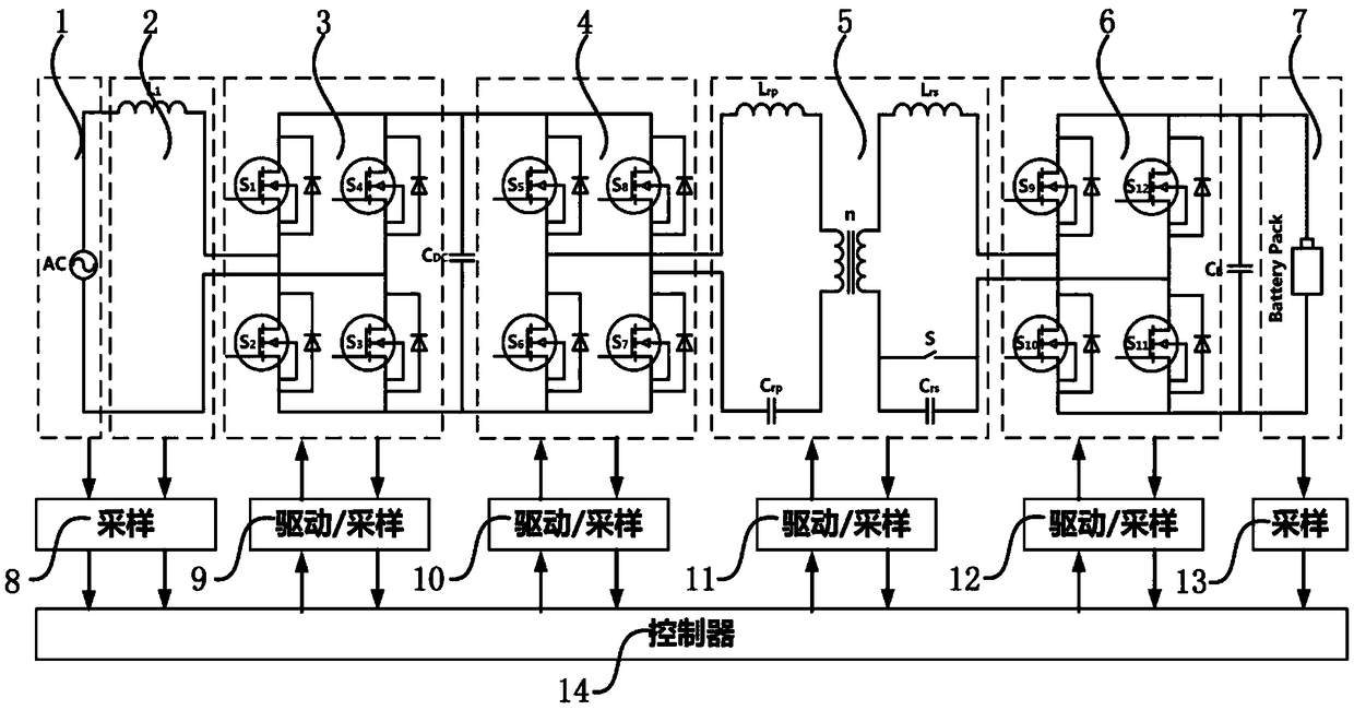
[0050] This embodiment provides an electric vehicle energy transmission system, such as figure 1 As shown, the electric vehicle energy transmission system includes an AC power supply 1, an inductance module 2, a first full-bridge rectification and inverter module 3, a second full-bridge rectification and inverter module 4, a transformer and a resonance compensation module 5, a Three full-bridge rectification inverter module 6 and power battery module 7, wherein: the transformer and resonance compensation module 5 includes a transformer, a first inductance Lrp, a second inductance Lrs, a first capacitor Crp, a second capacitor Crs and a first switch S; the input end of the primary side of the transformer is connected to the first inductor Lrp, the output end of the primary side of the transformer is connected to the first capacitor Crp; the input end of the secondary side of the transformer is connected to the second The inductor Lrs, the output end of the secondary side of the...

Embodiment 2

[0058] This embodiment also provides an electric vehicle energy transmission method based on the electric vehicle energy transmission system in the previous embodiment, including:

[0059] In the first forward charging mode, the first switch is closed, the first full-bridge rectifier and inverter module works in power factor correction mode, and the second full-bridge rectifier and inverter module works in pulse frequency modulation / LLC control mode, so The third full-bridge rectification and inverter module works in active rectification mode or passive rectification mode;

[0060] In the second forward charging mode, the first switch is turned off, the first full-bridge rectifier and inverter module works in the power factor correction mode, the second full-bridge rectifier and inverter module works in the quasi-resonant control mode, and the operating frequency for:

[0061] The third full-bridge rectification and inverter module works in PWM control mode or passive recti...


PUM


Abstract

The invention provides an electric automobile energy transmission system and transmission method, wherein the electric automobile energy transmission system comprises an alternating-current power supply, an inductance module, a first full-bridge rectification inversion module, a second full-bridge rectification inversion module, a transformer and resonance compensation module, a third full-bridgerectification inversion module and a power battery module which are connected in sequence, wherein the transformer and resonance compensation module comprises a transformer, a first inductor, a secondinductor, a first capacitor, a second capacitor and a first switch; the input end of the primary side of the transformer is connected with the first inductor, and the output end of the primary side of the transformer is connected with the first capacitor; the input end of the secondary side of the transformer is connected with the second inductor, and the output end of the secondary side of the transformer is connected with the second capacitor and the first switch which is connected with the second capacitor in parallel.

Description

technical field [0001] The invention relates to the technical field of electric vehicles, in particular to an electric vehicle energy transmission system and transmission method. Background technique [0002] The on-board charger is mainly used to provide electric energy for electric vehicles (EV / PHEV). The on-board charger is generally a two-stage circuit. The first stage is the PFC (power factor correction) link, and the second stage is the DC / DC link. The DC / The LLC topology is the most widely used DC part structure, but with the continuous development of new energy vehicle technology, the power supply between the power battery pack to non-vehicle loads (V2L), the power battery pack to the grid (V2G) or the power battery pack Therefore, in addition to meeting the normal charging needs of electric vehicles, the on-board charger should also take into account the reverse charging function. The prior art in this area mainly has following deficiencies at present: [0003] (...

Claims


Application Information

Patent Timeline
Patent Type & Authority Applications(China)
IPC IPC(8): H02J7/02H02M3/335B60L11/18
CPCH02J7/025H02M3/33592Y02T10/70Y02T10/7072Y02T10/72Y02T10/92Y02T90/14
Inventor 王振世徐玮邱松子金鼎成
Owner UNITED AUTOMOTIVE ELECTRONICS SYST
Why Eureka
Try Eureka