Excimer laser oscillation device having gas recycle function

A technology of excimer laser and oscillation device, which is applied in the direction of laser monitoring device, test gas existence, laser, etc., can solve the problem of not having circulation function and so on

Active Publication Date: 2018-12-07
LAIR LIQUIDE SA POUR LETUDE & LEXPLOITATION DES PROCEDES GEORGES CLAUDE
View PDF10 Cites 3 Cited by
  • Summary
  • Abstract
  • Description
  • Claims
  • Application Information

AI Technical Summary

Problems solved by technology

[0002] Conventional excimer laser oscillators do not have a circulation function for the laser gas (gas of the laser medium) used in the oscillator, and in addition to the vibration device, it is necessary to remove gas discharged to the outside of the system of the excimer laser oscillator. Recovery system for impurities in exhaust gas (used laser gas) (also called neon gas recovery system)

Method used


Image

  • Excimer laser oscillation device having gas recycle function
  • Excimer laser oscillation device having gas recycle function
  • Excimer laser oscillation device having gas recycle function

Examples


Embodiment approach 1

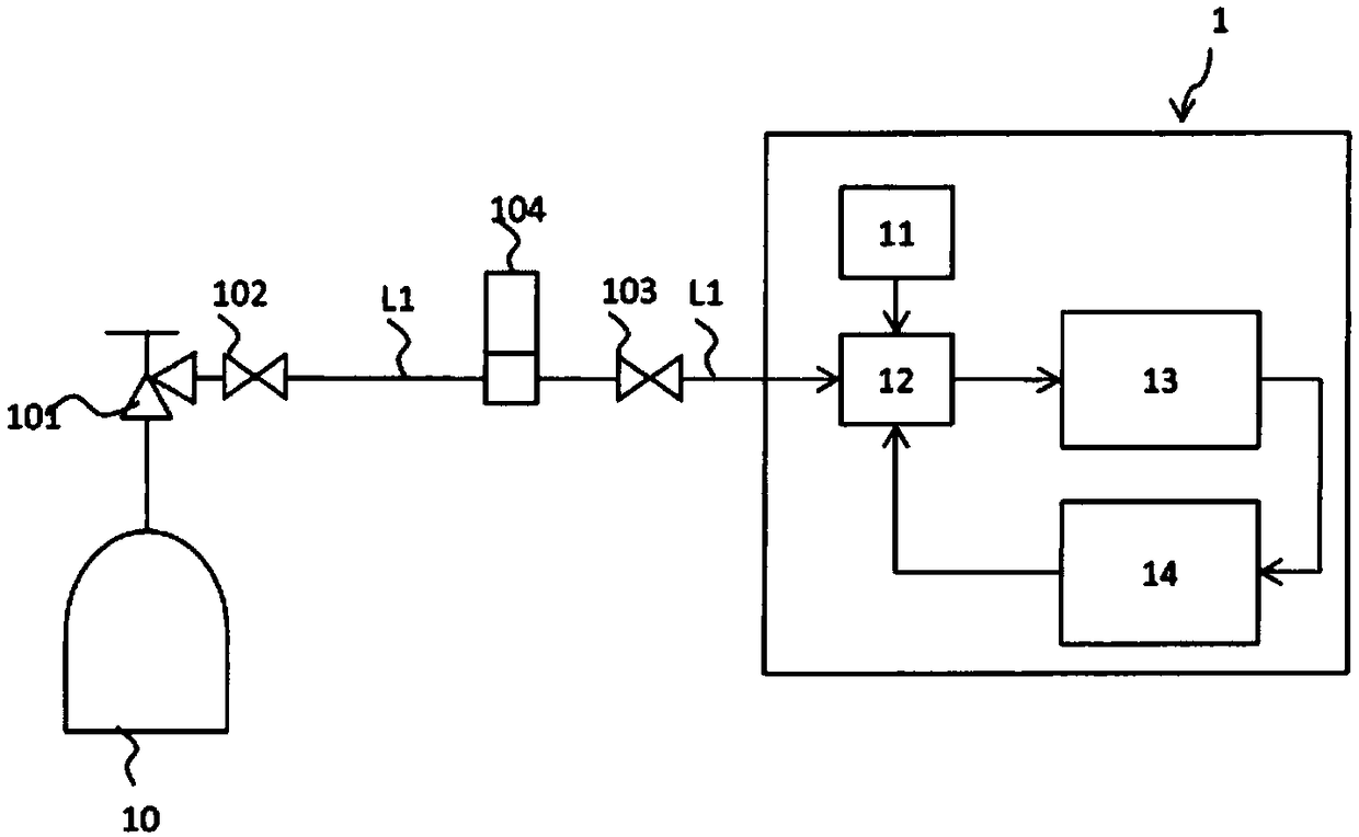
[0180] use Figure 1A , 1B The excimer laser oscillator 1 according to Embodiment 1 will be described.

[0181]The excimer laser oscillator is, for example, a krypton-fluorine (KrF) excimer laser oscillator, an argon-fluorine (ArF) excimer laser oscillator, or an argon-xenon-fluorine (Ar / X·F) excimer laser oscillator.

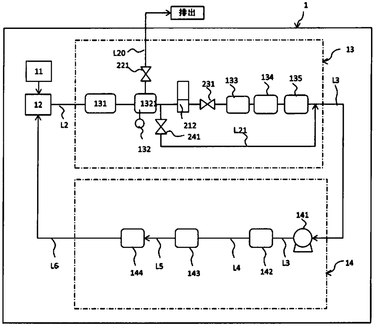
[0182] The excimer laser oscillator 1 of Embodiment 1 is provided in the system of the excimer laser oscillator 1: the interior is filled with a halogen gas (such as fluorine), a rare gas (such as krypton, argon, xenon), a buffer gas ( For example, an oscillation chamber 12 of laser gas such as neon, helium, and chlorine; a first impurity removal device 13 that removes impurities in exhaust gas discharged from the oscillation chamber 12; A second impurity removal device 14 for removing impurities from the purified gas.

[0183] The oscillation chamber 12 is filled with a predetermined pressure and a predetermined amount of laser gas. In this state, the high-...

Embodiment approach 2

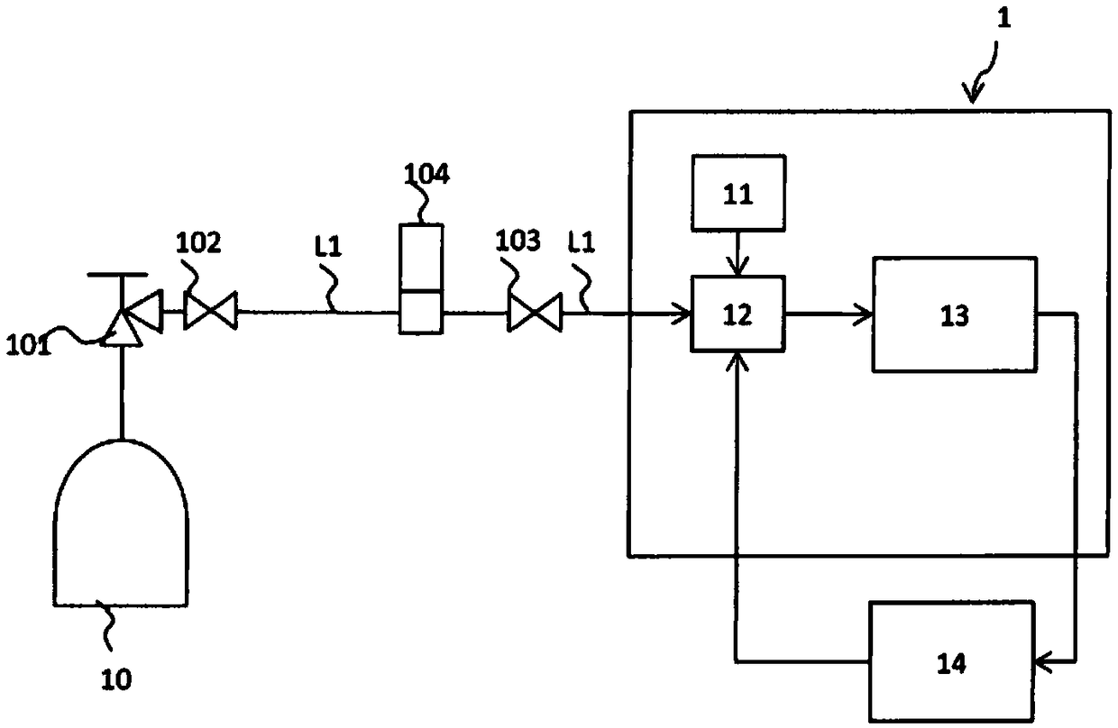
[0228] use Figure 2A , 2B An excimer laser oscillator 1 according to Embodiment 2 will be described. For the same structure as that of Embodiment 1, description thereof will be omitted or simplified. The excimer laser oscillation device 1 of Embodiment 2 is, for example, Figure 2A As shown, the first impurity removal device 13 is provided in the system, and the second impurity removal device 14 is arranged outside the system.

[0229] Such as Figure 2B As shown, the second impurity removal device 14 (compressor 141 , first removal unit 142 , second removal unit 143 , purified gas buffer tank 144 ) is arranged outside the system of the excimer laser oscillator 1 .

Embodiment approach 3

[0231] use image 3 An excimer laser oscillator according to Embodiment 3 will be described. Descriptions of the same configurations as those in Embodiments 1 and 2 are sometimes omitted or simplified. The difference from Embodiments 1 and 2 is that the structure of the second impurity removing device 14 has a xenon gas removing unit 70 and an auxiliary xenon gas supply function. When the xenon gas in the exhaust gas is removed and used as a laser gas component, the second impurity can be easily removed by the second removal unit 143. That is, the second impurity removing device 14 may be arranged inside or outside the system of the excimer laser oscillator.

[0232] The xenon gas removal unit 70 is arranged in the subsequent stage of the first removal unit 142 to remove xenon gas. The xenon removal unit 70 is a xenon removal device filled with activated carbon. The purified gas that has passed through the xenon removal unit 70 is sent to the second removal unit 143.

[0...


PUM


Abstract

The invention aims to set a removal function of removing impurities from waste gas including rare gases (such as argon, xenon, krypton and the like) used by an excimer laser oscillation device in a system of the excimer laser oscillation device. The invention provides the excimer laser oscillation device having the gas recycle function. The system of the excimer laser oscillation device is provided with an oscillation chamber filled with laser gases including halogen gas, rare gas and cushion gas and a first impurity removal device removing impurities in waste gas discharged from the oscillation chamber.

Description

technical field [0001] The present invention relates to an excimer laser oscillation device capable of removing impurities in exhaust gas discharged from an excimer laser oscillation chamber. The neon gas of xenon gas and argon gas, and the neon gas containing xenon gas are recovered and reused as recycle gas. Background technique [0002] Conventional excimer laser oscillators do not have a circulation function for the laser gas (gas of the laser medium) used in the oscillator, and in addition to the vibration device, it is necessary to remove gas discharged to the outside of the system of the excimer laser oscillator. A recovery system (also known as a neon gas recovery system) for impurities in the waste gas (used laser gas). Generally, the mainstream technology is to use various separation technologies such as low-temperature separation to separate the impurities and rare gases in the exhaust gas, purify it as high-purity neon gas with a neon content of more than 99%, a...

Claims


Application Information

Patent Timeline
Patent Type & Authority Applications(China)
IPC IPC(8): B01D53/75B01D53/32C01B23/00
CPCB01D53/32B01D53/75C01B23/0036B01D2259/808H01S3/104H01S3/0014H01S3/10069H01S3/225H01S3/036H01S3/08H01S3/0975G01N31/223H01S3/2207H01S3/09705H01S3/134
Inventor 小浦辉政松本幸二野泽史和筿原悠介
Owner LAIR LIQUIDE SA POUR LETUDE & LEXPLOITATION DES PROCEDES GEORGES CLAUDE
Why Eureka
Try Eureka