
Solder joint inspection method for electric resistance welding based on full focusing synthetic aperture technology

A synthetic aperture, all-focusing technology, used in measuring devices, analyzing solids using sonic/ultrasonic/infrasonic waves, and using sonic/ultrasonic/infrasonic waves for material analysis, etc. Achieve the effect of improving horizontal and vertical resolution, improving vertical resolution, and accurate defect positioning

Inactive Publication Date: 2018-12-07
NANCHANG HANGKONG UNIVERSITY
View PDF1 Cites 2 Cited by
  • Summary
  • Abstract
  • Description
  • Claims
  • Application Information

AI Technical Summary

Problems solved by technology

Due to the small area of ​​the welding nugget, if the welding process is poorly controlled, it is easy to cause defects such as virtual welding without nugget, over-burning, burn-through, undercut, depression, cracks (cold cracks, hot cracks and reheat cracks), etc. It is easy to cause poor welding appearance and reduced joint strength, which can cause problems such as tearing
[0004] Therefore, after the metal plate welding is completed, it is necessary to carry out quality inspection on it. The traditional quality inspection cannot make a direct quality judgment on the welding. Usually, the method of random inspection is used to conduct destructive mechanical tests. When the test is qualified, the workpiece is also damaged. caused irreversible damage

Method used


Image

  • Solder joint inspection method for electric resistance welding based on full focusing synthetic aperture technology
  • Solder joint inspection method for electric resistance welding based on full focusing synthetic aperture technology

Examples


Embodiment Construction

[0027] The following will clearly and completely describe the technical solutions in the embodiments of the present invention with reference to the accompanying drawings in the embodiments of the present invention. Obviously, the described embodiments are only some, not all, embodiments of the present invention. Based on the embodiments of the present invention, all other embodiments obtained by persons of ordinary skill in the art without making creative efforts belong to the protection scope of the present invention.

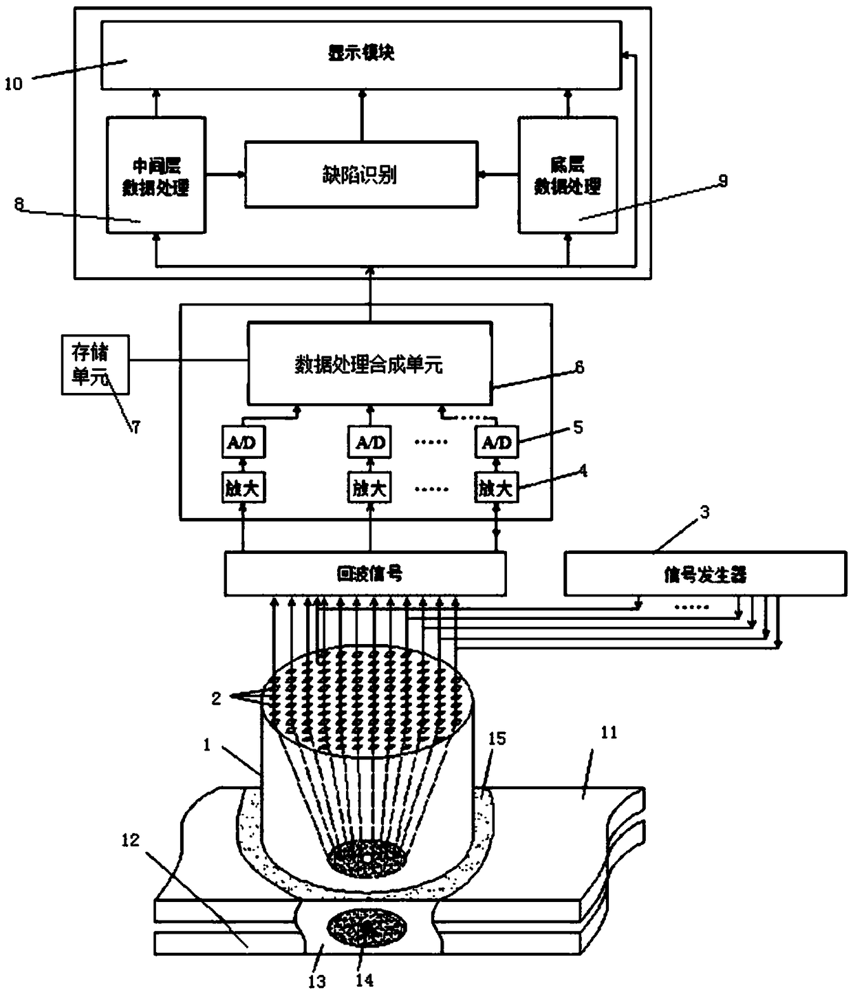
[0028] A resistance welding spot detection method based on omni-focus synthetic aperture technology disclosed by the present invention comprises the following steps:

[0029] a. Coating couplant on the surface of the test area of ​​the workpiece to be tested, placing the phased array probe of the detector on the surface of the test area, adjusting the frequency, and starting the signal generator to send the excitation signal;

[0030] b. The composite chip tra...


PUM


Abstract

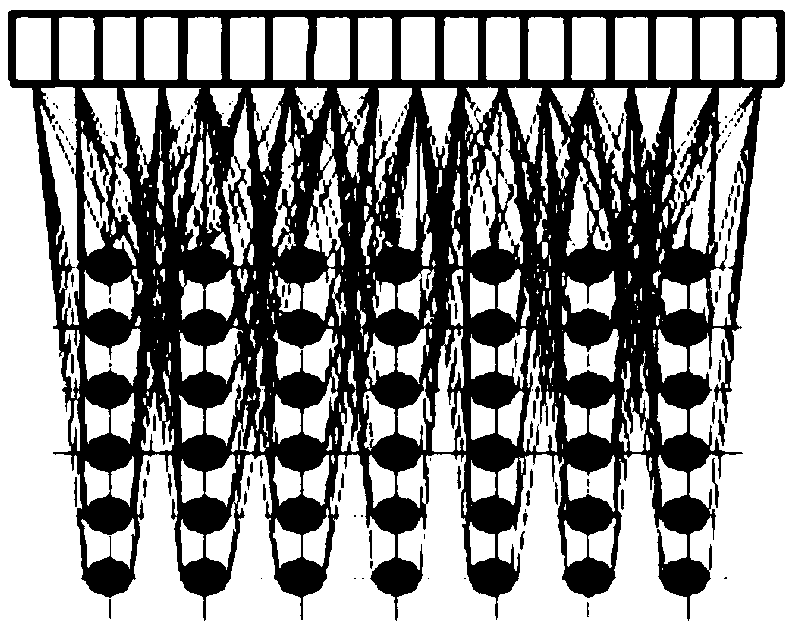
The invention discloses a solder joint inspection method for electric resistance welding based on a full focusing synthetic aperture technology. The method comprises the following steps: placing a phased array probe in a to-be-tested area, transmitting a pulsed electrical signal to each composite material wafer of the phased array probe by a pulse emission receiver, generating ultrasonic waves bya composite material wafer transducer, enabling the ultrasonic waves to generate reflected echo signals on a to-be-tested workpiece surface, a first metal layer bottom surface, a fusion zone bottom surface and the like, receiving the echo signals by the composite wafer transducer, feeding the signals into an amplifying circuit and an AD (Analog-Digital) conversion circuit in groups for performingsignal processing, feeding into a data processing composite unit, performing stack imaging on the echo signals by utilizing a full focusing synthetic aperture algorithm, performing three-dimensional imaging, displaying the image by a display module, obtaining the fusion zone size, and obtaining the nugget size by virtue of database comparison; and in addition, performing pseudo-color processing onthe obtained three-dimensional images, separating the solder side bottom layer from the fusion zone, recognizing the defect parts, and finally performing defect part display by the display module.

Description

technical field [0001] The invention relates to the technical field of ultrasonic industrial non-destructive testing, in particular to a resistance welding spot detection method based on an all-focus synthetic aperture technology. Background technique [0002] Resistance welding is the most commonly used welding method in sheet metal welding. It has the advantages of short heating time, concentrated heat, small heat-affected zone, small deformation and stress, no need to arrange calibration and heat treatment procedures after welding; no consumables are required, and the welding cost is low. ; Simple operation, easy to realize mechanization and automation, improve working conditions; high productivity, and no noise and harmful gases, in mass production, it can be compiled into the assembly line together with other manufacturing processes and many other advantages. Therefore, resistance welding is an irreplaceable main welding method in sheet metal welding, and its welding qu...

Claims


Application Information

Patent Timeline
Patent Type & Authority Applications(China)
IPC IPC(8): G01N29/06
CPCG01N29/069G01N2291/2675
Inventor 常俊杰李媛媛王焜
Owner NANCHANG HANGKONG UNIVERSITY
Learn More