
Method for improving resin transfer molding quality of carbon fiber composite material thin-wall part

A technology for resin transfer molding and composite material components, which is applied in the field of carbon fiber reinforced resin matrix composite material molding, can solve the problems of reducing the strength and service life of components, poor molding quality of components, and fast injection speed, etc. Molding quality, effect of reducing residual air bubbles

Active Publication Date: 2018-12-11
WUHAN UNIV OF TECH
View PDF1 Cites 2 Cited by
  • Summary
  • Abstract
  • Description
  • Claims
  • Application Information

AI Technical Summary

Problems solved by technology

[0003] However, there are still two deficiencies in the traditional RTM molding of carbon fiber composite thin-walled components: 1. Thin-walled curved parts have small-scale features and complex structures. When the filling pressure is low, the contact between the resin and the mold is insufficient, and the resin filling effect Poor, may produce wrinkles, holes and other defects, affecting the surface finish of the molded test piece; 2. Due to the fast injection speed and the complex structure of the component, the residual small volume of air bubbles in the resin material cannot be discharged during low-pressure injection, which affects the molding quality of the component. Reduce the strength and service life of components
[0004] Some scholars have proposed a high-pressure RTM molding method (HP-RTM) to solve this problem, but when HP-RTM is used, the pressure is about 2-30 MPa. During the high-pressure injection process, the carbon fiber is easily deflected and entangled by the high-speed flowing resin material. knots, non-uniform distribution, the quality of the resulting components is poor, and cannot meet the requirements of use

Method used


Image

  • Method for improving resin transfer molding quality of carbon fiber composite material thin-wall part

Examples


Embodiment 1

[0028] Now take the automobile carbon fiber composite material front engine cover product as an example to further elaborate the present invention.

[0029] The carbon fiber material used in step S1 is a multilayer carbon fiber cloth arranged in the manner of (0,90), (±45), (0,90), (±45), (0,90). Its density is 350g / m 2 , after laser cutting to meet the molding requirements.

[0030] The mold used in step S1 is divided into upper and lower molds, and before injecting resin, the mold is preheated at 80±5°C.

[0031] The resin system used in step S2 is 605 epoxy resin, the curing agent is T31 curing agent, the resin and the curing agent are mixed in a ratio of 1:1, the resin material content (weight percentage) is 50-55%, and the carbon fiber material content is 45-50%. 50%.

[0032] The ratio of excess resin injected in step S2 is 1.05-1.10.

[0033] In step S2, the resin is injected using a low-pressure resin pump station, and the injection pressure is 1-2 MPa.

[0034] T...


PUM


Abstract

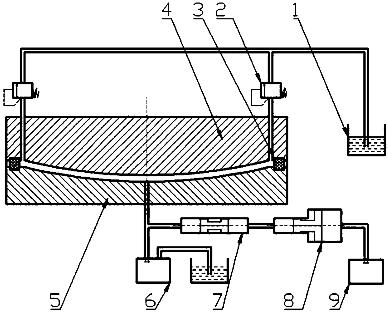
The invention provides a method for improving the resin transfer molding (RTM) quality of a carbon fiber composite material thin-wall part. The method comprises the following steps: 1) paving carbon fiber cloth in mold equipment; 2) regulating a resin pressure overflowing valve to a low threshold value (1 to 2MPa); filling low-pressure resin into a mold by adopting a low-pressure pump station andoverflowing on an overflowing valve after overflowing pressure is reached; 3) adjusting the overflowing valve to a high threshold vale (100 to 200MPa) and closing the resin low-pressure pump station;heating the mold through a heating device; 4) starting a high-pressure pump station and applying pressure through an ultrahigh-pressure supercharger; applying quasi-static ultrahigh pressure of 100 to200MPa to excessive resin in the mold through a pressure valve; carrying out heat insulation and pressure maintenance; curing and molding a resin material; and 5) opening the mold and taking out a molded carbon fiber member. The method provided by the invention can be used for reducing the porosity, improving the smooth finish, promoting small-size characteristics of resin filling parts and remarkably improving the RTM molding quality of the member.

Description

technical field [0001] The invention belongs to the technical field of forming carbon fiber reinforced resin-based composite materials, and in particular relates to a method for improving the quality of resin transfer molding of thin-walled carbon fiber composite materials. Background technique [0002] Carbon fiber reinforced composite material is an advanced lightweight material with low density, high strength, corrosion resistance, impact resistance and other characteristics. In recent years, it has been widely used in large aircraft, ships and high mobility off-road vehicles. One of the forming methods of carbon fiber composite thin-walled components is resin transfer molding, or RTM for short. The process steps are to inject the resin into the high-temperature mold by vacuuming, pressurizing, etc., the resin completes the infiltration of the preformed matrix during the flow process, and obtains the thin-walled curved surface parts of carbon fiber composite materials thr...

Claims


Application Information

Patent Timeline
Patent Type & Authority Applications(China)
IPC IPC(8): B29C39/10B29K63/00
CPCB29C39/10B29C2791/002B29K2063/00
Inventor 华林陈一哲李健王辉胡志力
Owner WUHAN UNIV OF TECH
Learn More