
Artificial mitral valve intervention replacement device and intervention method thereof

A mitral valve and artificial valve technology, applied in the field of artificial mitral valve interventional replacement devices, can solve problems such as ventricular damage, valve failure, regurgitation, etc., and achieve the effect of improving safety

Active Publication Date: 2018-12-18
谭雄进
View PDF8 Cites 6 Cited by
  • Summary
  • Abstract
  • Description
  • Claims
  • Application Information

AI Technical Summary

Problems solved by technology

Another example is the patent document whose application publication number is CN201711162783 and which is named "Mitral valve parking device, system and method", as shown in Figure 10-12, the helical anchor is provided with a hook-shaped bracket for fixing the anchor , this fixation method will also cause ventricular damage
In the prior art, the working principle of three arc-shaped leaflets expanding and closing under the impact of blood flow is mostly used. This closing mode must use biological materials, such as bovine pericardium and pig heterologous valves, because non-biological synthetic The material will undergo fatigue deformation during the closing process of long-term blood flow impact expansion, and the slight deformation will cause the three valve leaflets to not fit tightly, and then regurgitation will occur. However, there is a risk of heterogeneity in the use of biological materials, and it is inevitable in the long run. Calcification leads to valve failure, and the service life of the existing artificial biological valve is about ten years
[0004] In addition, the existing mitral valve anchoring devices all squeeze the natural valve leaflets on the side wall of the ventricle, replacing the natural valve leaflets with artificial valve leaflets, so that the natural valve leaflets completely lose their own functions

Method used


Image

  • Artificial mitral valve intervention replacement device and intervention method thereof
  • Artificial mitral valve intervention replacement device and intervention method thereof
  • Artificial mitral valve intervention replacement device and intervention method thereof

Examples


Embodiment 1

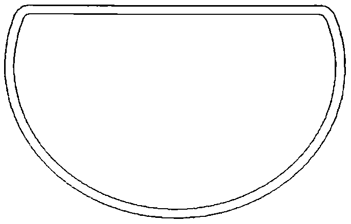
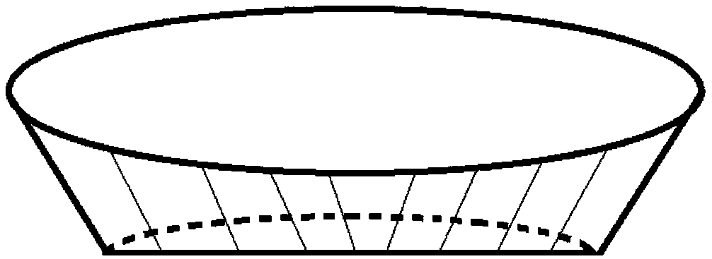
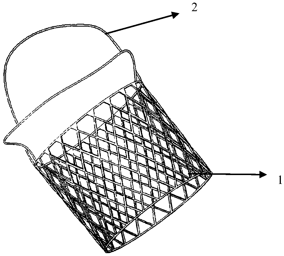
[0038] An artificial mitral valve interventional replacement device, such as Figure 1-3 As shown, it includes the support body 1 and the artificial valve leaflet 2, and the opening on the upper edge of the support body is circular, elliptical, or D-shaped, or is set as a special shape to adapt to the spatial structure of the left atrium above the patient's mitral valve according to the patient's CT image. The cross-section of the lower edge is "D" shape, and the circumference gradually decreases from the top to the bottom of the cone structure, and the lower edge of the support body is connected with several artificial valve leaflets. After the D-shaped lower edge of the support body of the present invention is embedded in the valve annulus, the upper part of the support body can closely fit the patient's left atrium.

[0039] The support body is a deformable material. Preferably, the support body can be a mesh structure woven with memory alloy wires, or other elastically def...

Embodiment 2

[0048] Such as Figure 4-5 As shown, preferably, the upper edge of the support body is supported in the left atrium above the mitral valve annulus, and the artificial valve leaflet is prolapsed into the ventricle and can move with the natural valve leaflet movement.

[0049] A number of arresting cables 4 are arranged in the support body to prevent the leaflets from excessively floating to the left atrium, so that each artificial valve leaflet is joined to each other on the arresting cable plane. The present invention does not limit the structure and position of the arresting cable, and the structure that can prevent the valve leaflet from floating beyond the upper edge opening of the support body should be understood as the setting method of the arresting cable of the present invention. For example, several arresting cables can be parallel to each other and arranged on the same plane, or each arresting cable is sunken toward the left ventricle to form two or several mating pl...

Embodiment 3

[0055] An interventional method of an artificial mitral valve interventional replacement device, comprising the following steps:

[0056] Step 1: apical puncture, the catheter and guide wire are sent from the left ventricle to the left atrium through the bicuspid opening;

[0057] In step 2, the artificial mitral valve interventional replacement device is loaded into the corresponding delivery system, sent into the delivery system along the guide wire, and after the delivery system is sent into the left atrium, the guide wire is withdrawn from the body;

[0058] Step 3 Under the guidance of ultrasound, adjust the direction of the delivery system through the mark on the delivery system, so that the mark faces the midpoint of the anterior mitral annulus, so as to ensure that the position of the artificial valve leaflet corresponds to the position of the natural valve leaflet, and the artificial valve leaflet can be aligned with the natural valve leaflet. The natural leaflets mov...


PUM

PropertyMeasurementUnit
Long trailaaaaaaaaaa
Short diameteraaaaaaaaaa
Heightaaaaaaaaaa

Abstract

The invention relates to an artificial valve intervention replacement device applied to mitral insufficiency. The device comprises a supporting body and multiple artificial valves, the lower edge of the supporting body is of a conical cylinder structure with a D-shaped cross section, multiple stopping ropes are arranged in the supporting body, and the artificial valves are connected to the lower edge and can move along with motion of the natural valve of a patient. According to the intervention replacement device, the functions of the left chamber outflow channel and the aortic valve are not influenced, the function of the natural valve of the mitral valve is reserved, the natural blood flow is used for driving the artificial valve and the aortic valve to move in the same direction, and the artificial valve can be completely closed at the contraction period to prevent backflow of the mitral valve.

Description

technical field [0001] The invention belongs to the field of biomedical devices, and in particular relates to an artificial mitral valve interventional replacement device and an interventional method thereof. Background technique [0002] Mitral regurgitation (MitraI Regurgitation, MR) is a common heart valve disease, the basic pathological change is mitral regurgitation. When the left ventricle contracts, the blood flows from the left ventricle into the aorta and enters the left atrium with less resistance through the incompetent mitral valve, and the regurgitation flow into the left atrium can reach more than 50% of the left ventricular output. Elevated left atrial pressure can cause increased pressure in the pulmonary veins and swollen capillaries, which in turn dilate and congest. At the same time, the diastolic volume load of the left ventricle increases and the left ventricle expands. Patients with advanced mitral regurgitation may develop pulmonary hypertension and ...

Claims


Application Information

Patent Timeline
IPC IPC(8): A61F2/24
CPCA61F2/2418A61F2/2436A61F2/2448A61F2/2466
Inventor 潘湘斌谭雄进
Owner 谭雄进
Learn More