Radial Displacement Observation Method for Low Speed and Zero Speed Rotor of Bearingless Flux Switching Motor

A magnetic flux switching motor, radial displacement technology, applied in the direction of electronic commutation motor control, generator control, motor control, etc., to avoid adverse effects, reduce weight, and simplify motor design.

Active Publication Date: 2018-12-18
FUZHOU UNIV
View PDF5 Cites 10 Cited by
  • Summary
  • Abstract
  • Description
  • Claims
  • Application Information

AI Technical Summary

Problems solved by technology

[0005] In view of this, the purpose of the present invention is to provide a method for observing the radial displacement of the low-speed and zero-speed rotor of a bearingless flux switching motor, which uses the high-frequency component of the windin...

Method used


Image

  • Radial Displacement Observation Method for Low Speed and Zero Speed Rotor of Bearingless Flux Switching Motor
  • Radial Displacement Observation Method for Low Speed and Zero Speed Rotor of Bearingless Flux Switching Motor
  • Radial Displacement Observation Method for Low Speed and Zero Speed Rotor of Bearingless Flux Switching Motor

Examples


Embodiment 1

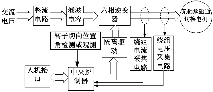
[0057] This embodiment provides a drive system hardware structure such as image 3 As shown, it includes: rectifier circuit, filter capacitor, six-phase inverter, bearingless flux switching motor, winding current acquisition circuit, winding voltage acquisition circuit, isolation drive, central controller, and man-machine interface. If there is a DC power supply, the rectification and filtering links can also be omitted. The power tube in the inverter adopts IGBT or MOFET, and the central controller adopts DSP or single-chip microcomputer. The winding current acquisition circuit is formed by combining a Hall current sensor and an operational amplifier, or by combining a winding string power resistor followed by a differential operational amplifier. The electrical isolation between the control loop and the main loop can be effectively realized by using the Hall solution, and the cost of the drive system can be reduced by using the winding string power resistor solution. The w...

Embodiment 2

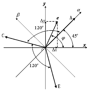
[0061] Define the coordinate system as Figure 4 shown. Among them, e is the rotor offset vector, and its projection on the xy axis is Δx and Δy, respectively. A, C, and E are the axes of the windings A, C, and E respectively, and are αβ static rectangular coordinate systems, where α coincides with the axis of the A-phase winding. The double salient pole structure of BFSM is equivalent to the hidden pole structure. Suppose the air gap length of the hidden pole motor after equivalent is l 0 , and the area of ​​each pole is S, then the air gap reluctance R is as follows:

[0062]

[0063] Among them, μ 0 is the vacuum permeability.

[0064] The corresponding air gap permeability Λ is as follows

[0065]

[0066] Assuming that the air gap length is shortened by Δl due to rotor eccentricity, the corresponding air gap permeance Λ is as follows:

[0067]

[0068] suppose as Figure 4 As shown, the rotor along the Angular direction eccentric e, then mapped to the x...


PUM


Abstract

The invention relates to a method for observing the radial displacement of a low-speed and zero-speed rotor of a bearingless flux switching motor, wherein an anti-phase high-frequency current is injected into a spatially symmetrical winding; The phase winding voltage of bearingless flux switching motor (BFSM) is used to calculate the high frequency component of the phase winding voltage. Calculating the sum of high frequency components of voltage at two windings with 180 degrees of spatial symmetry; Transforming the sum and amplitude of the high frequency components of the voltage of each pairof winding terminals in a space symmetry in a natural coordinate system to a rectangular alpha beta coordinate; According to the relationship between alpha beta coordinate system voltage and rotor radial displacement deltax, delta y, the rotor radial displacement deltax, deltay is observed. The radial displacement deltax, deltay of the rotor can be fed back to the radial suspension and tangentialrotation control of the rotor to realize the control of the rotor suspended in the stator center. As that manufacture cost of the motor and the controller is not increased, the high-frequency component of the winding voltage of the motor itself is utilized to observe the radial displacement of the rotor.

Description

technical field [0001] The invention relates to a method for observing the radial displacement of a low-speed and zero-speed rotor of a bearingless magnetic flux switching motor. Background technique [0002] The bearingless flux switching motor adopts the stator permanent magnet structure, which is conducive to the heat dissipation of the permanent magnet. It has the outstanding advantages of high efficiency, reducing the risk of demagnetization of the permanent magnet due to temperature rise, and no pollution. It is used in high-speed, ultra-high-speed, large-capacity, clean It has extremely high application value in the field of motor drive. [0003] In order to realize the stable suspension of the rotor in the center, it is usually necessary to control two radial displacement degrees of freedom. In order to realize the radial displacement control, the rotor radial displacement feedback is usually used to form the rotor suspension closed-loop control. At present, the ra...

Claims


Application Information

Patent Timeline
IPC IPC(8): H02P6/18H02P21/18
CPCH02P6/183H02P21/18H02P2203/11
Inventor 周扬忠林碧云钟天云屈艾文
Owner FUZHOU UNIV
Why Eureka
Try Eureka