Fresnel zone plate spectrum confocal measurement method

A Fresnel zone plate and spectral confocal technology, which is applied in the field of precision measurement, can solve the problems of not using polychromatic light illumination, etc., and achieve the effects of flexible design, improved detection accuracy, and simplified device structure

Active Publication Date: 2018-12-21
XI AN JIAOTONG UNIV
View PDF4 Cites 7 Cited by
  • Summary
  • Abstract
  • Description
  • Claims
  • Application Information

AI Technical Summary

Problems solved by technology

[0004] Chinese invention patent (application number: 201611127494.5) proposes a wavelength-scanning confocal micro-displacement measurement device and method, which uses a Fresnel zone plate to change the wavelength by stepping, and then changes the focus position to scan the sample to measure t

Method used


Image

  • Fresnel zone plate spectrum confocal measurement method
  • Fresnel zone plate spectrum confocal measurement method
  • Fresnel zone plate spectrum confocal measurement method

Examples


Embodiment Construction

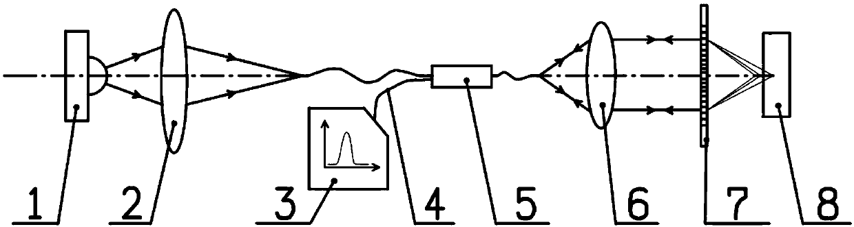
[0048] The invention provides a Fresnel zone plate spectral confocal measurement method, which utilizes the principle of spectral confocal measurement, and produces corresponding to different The color band of the wavelength is different from the traditional spectral confocal measurement method that uses lenses or lens groups for dispersion focusing, which significantly simplifies the structure of the spectral confocal measurement device, and the design is more flexible. Precise measurement of displacement, especially three-dimensional measurement of transparent objects with low reflectivity.

[0049] see figure 1 , a Fresnel zone plate spectrum confocal measurement device of the present invention, comprising a composite light source 1, a lens group 2, a spectrometer 3, an optical fiber 4, a fiber coupler 5, a collimating lens 6, and a Fresnel zone plate 7 , standard flat reflector or sample 8; fiber coupler 5 is arranged between lens group 2 and collimator lens 6, Fresnel zo...


PUM


Abstract

The invention discloses a Fresnel zone plate spectrum confocal measurement method. The method comprises the following steps: constructing a spectrum confocal measurement device, performing direct chromatic dispersion focusing by using the Fresnel zone plate which replaces a lens or a lens group; monitoring an axial location of a standard plane mirror, calibrating linear axial focusing range of theFresnel zone plate and the wavelength-location relation of the spectrum confocal measurement device; replacing the standard planar mirror as the to-be-measured sample, placing a to-be-measured surface of the sample in the measurement range of the device to perform measurement; performing the chromatic dispersion on the composite light source along the axial direction of the Fresnel zone plate, thereby producing color zones corresponding to different wavelengths, returning the light field with the wavelength corresponding to the focal point focused on the sample surface along an original lightpath, enabling a spectrograph to detect a return signal intensity point diffusion function, computing a peak coordinate location by utilizing a centroid method, and obtaining the location informationof the sample measurement point according to the wavelength-location calibration curve. Compared with the traditional spectrum confocal measurement, the method has the advantages of being simple in structure, flexible in design, and low in cost.

Description

technical field [0001] The invention belongs to the technical field of precision measurement, and in particular relates to a Fresnel zone plate spectral confocal measurement method. Background technique [0002] Confocal Microscopy (Confocal Microscopy) is the most typical method to achieve optical tomography. The earliest confocal microscopy imaging device was proposed in 1961 by M. Invention patent right. Spectral confocal technology uses the confocal principle of confocal microscopy technology and a measurement method that combines the principle of dispersion focusing. Compared with confocal microscopy technology, spectral confocal technology does not require an axial scanning device and simplifies its structure. At present, spectral confocal technology has had a profound impact on modern biology and medicine, physics, chemistry, material science, nanotechnology, precision measurement and other fields. [0003] The prominent feature of the spectral confocal measurement ...

Claims


Application Information

Patent Timeline
IPC IPC(8): G01B11/00
Inventor 刘涛田博杨树明刘强王通刘康蒋庄德
Owner XI AN JIAOTONG UNIV
Why Eureka
Try Eureka