

Method and system for processing long pulse infrared non-destructive detection sequence image
An infrared image processing and infrared image technology, applied in image data processing, image enhancement, image analysis, etc., can solve problems such as unsuitable for carrying, unsuitable for industrial non-destructive testing, complex equipment, etc., to facilitate quantitative calculation and clearly display the shape of defects and position, the effect of eliminating noise
- Summary
- Abstract
- Description
- Claims
- Application Information
AI Technical Summary
Problems solved by technology
Method used
Image


Examples
Embodiment 1
[0225] The detection method and system of the present invention are used in the detection of a glass fiber laminate with a size of 200×150×6mm containing hole-type defects on the back, so as to determine the location of the defect and quantitatively measure the diameter and location of the hole defect on the back.
[0226] The physical picture of the sample is shown in Figure 3, and the defect distribution is as follows Figure 4a and Figure 4b As shown, the specific detection process is:
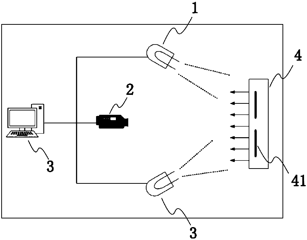
[0227] Fix the sample on the test platform, the detection surface is located directly in front of the infrared thermal imager, ensure that the sample and the infrared thermal imager are at the same level, the infrared thermal imager is 1.5m away from the sample surface, and the excitation device is to the sample surface 0.5m to ensure the best detection results.
[0228] Open the infrared image processing software (including the software of the above-mentioned sequential infrared image p...
Embodiment 2
[0235] The detection method and system of the present invention are used for the detection of a carbon fiber laminate sample, and the sample size is 250 * 80 * 4mm, 7a and Figure 7b It is a physical photo of the carbon fiber laminate, and the diameter and depth of the blind hole are detailed in Figure 8 , "D6H1.7" in the figure indicates that the diameter of the blind hole is 6mm, and the depth of the blind hole is 1.7mm, that is, the defect depth is 2.3mm (the plate thickness is 4mm).
[0236] According to the method provided by the invention, the specific measurement process is:
[0237] Before the experiment, paint the surface with matte black acrylic spray paint to maximize the absorption of excitation light energy and increase the emissivity.
[0238] Place the position of the thermal imaging camera and ensure that the surface of the sample is in the center of the field of view of the thermal imaging camera. Ensure that the sample and the thermal imaging camera are at ...
PUM
 Abstract
Description
Claims
Application Information