Partial vacuum laser welding and two-sided annealing device for aluminum alloys

A local vacuum and laser welding technology, which is applied in the field of aluminum alloy welding, can solve the problems that the mechanical properties of welded structural parts need to be strengthened, the processing of large-sized workpieces is inconvenient, and there is no welding seam modification, etc., to suppress photoplasma and metal vapor The effect of reducing pit defects on the weld surface and improving stability

Active Publication Date: 2018-12-25
GUANGDONG UNIV OF TECH
View PDF8 Cites 5 Cited by
  • Summary
  • Abstract
  • Description
  • Claims
  • Application Information

AI Technical Summary

Problems solved by technology

[0005] The search found that the patent "A Vacuum Electron Beam Welding Method for Aluminum Alloy" (Application No.: 201210433230.8) described that the welding workpieces are pressed into each other and placed in a vacuum chamber, and then preheated, pre-connected, and pierced by electron beam scanning. Through welding, and finally vacuum cooling can effectively improve the quality of the weld seam, but it is necessary to set up a vacuum environment for the entire welding furnace space, which increases the cost and is not convenient for processing large-sized workpieces
The patent "Welding Method of Aluminum Alloy Instrument Panel Crossbeam" (Application No.: 201110459261.6) describes the positioning welding of aluminum alloy before welding to remove the oxide film, which is easy to operate, but because there is no post-weld modification, the mechanical properties of the welded structural parts It needs to be strengthened

Method used


Image

  • Partial vacuum laser welding and two-sided annealing device for aluminum alloys
  • Partial vacuum laser welding and two-sided annealing device for aluminum alloys
  • Partial vacuum laser welding and two-sided annealing device for aluminum alloys

Examples


Embodiment Construction

[0024] The following will clearly and completely describe the technical solutions in the embodiments of the present invention in conjunction with the accompanying drawings in the embodiments of the invention. Obviously, the described embodiments are only some of the embodiments of the present invention, not all of them. Based on the embodiments of the present invention, all other embodiments obtained by persons of ordinary skill in the art without creative efforts fall within the protection scope of the present invention.

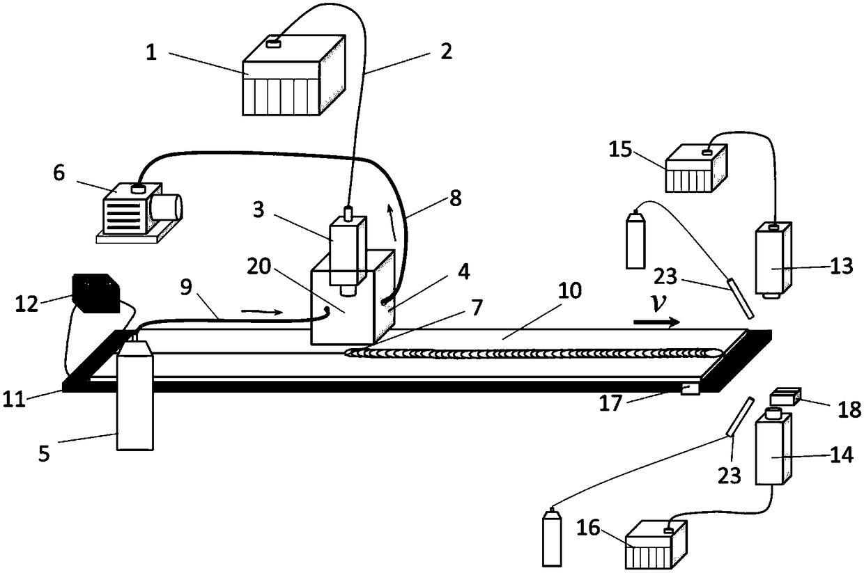
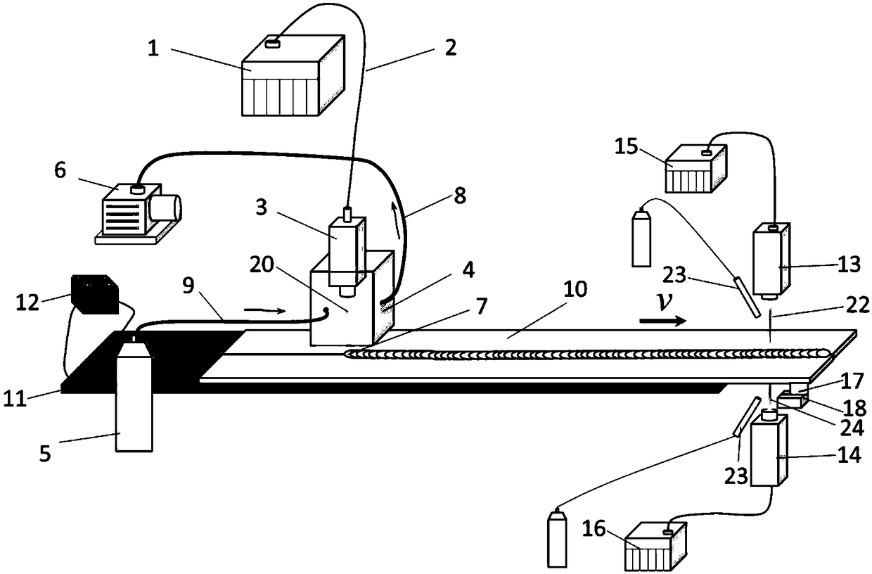
[0025] Such as figure 1 , 2 , 3, and 4, the device for partial vacuum laser welding and double-sided annealing of aluminum alloys, wherein, it includes a first laser (1), an optical fiber (2), a first focusing head (3), a welding plate (10), Resistance heating plate (11), heating power supply (12), thick copper plate (19), fixture (not shown in figure), drive member (not shown in figure), vacuum module; the first laser (1) communicates with the second thro...


PUM

PropertyMeasurementUnit
diameteraaaaaaaaaa
melting pointaaaaaaaaaa

Abstract

The invention discloses a partial vacuum laser welding and two-sided annealing device for aluminum alloys. The exhaust flow of an air outlet pipe of a partial vacuum chamber is larger than the intakeflow of an air inlet pipe, and a negative pressure environment is provided during welding; a resistance heating plate is arranged to preheat a welded plate, and a laser annealing module is arranged; after an aluminum alloy plate is welded with laser and is slightly cooled, laser annealing is carried out with the residual heat of preheating; and grain refinement and residual pressure layers are formed on the upper surface and the lower surface of a welded joint, and therefore the yield strength and tensile strength of the welded joint are improved. The ambient air pressure is reduced by the laser welding under partial vacuum, the discharging of bubbles in a molten pool is facilitated, pore defects are reduced, meanwhile the generation of a laser induced plasma and metal vapor is inhibited,and the inverse bremsstrahlung absorption for laser beam energy is reduced. In addition, the preheating treatment of the welded plate improves the stability of the welding process, and splashing is greatly reduced. The fish-scale patterns on the weld surface tend to be fine, and therefore the defect of pits in the weld surface is reduced.

Description

technical field [0001] The invention relates to the technical field of aluminum alloy welding, in particular to a device for partial vacuum laser welding and double-sided annealing of aluminum alloys. Background technique [0002] Laser welding technology is widely used in automobile manufacturing, pressure vessel manufacturing and other industries because of its high power density, small heat-affected zone, large weld depth-to-width ratio, no electromagnetic interference, and no magnetic deflection phenomenon. As the main means of civil transportation, automobiles are currently facing a major challenge to achieve lightweight under the premise of ensuring a sufficient safety factor. Through the comparison of production cost, parts quality, material utilization and other aspects, aluminum alloy has become an indispensable and important raw material for automobile production. Replacing traditional steel with aluminum alloy structure can reduce the weight of automobiles by 30%-...

Claims


Application Information

Patent Timeline
Patent Type & Authority Applications(China)
IPC IPC(8): B23K26/70C21D1/26C21D9/50C21D1/74
CPCC21D1/26C21D1/74C21D9/50B23K26/702
Inventor 丁树权游德勇
Owner GUANGDONG UNIV OF TECH
Why Eureka
Try Eureka