Manufacturing method of partition plate in multi-cylinder compressor

A compressor manufacturing method technology, applied in the field of compressors, can solve the problems of processing waste materials, harsh processing conditions, and low processing efficiency, and achieve the effects of reducing processing costs, good dimensional accuracy, and fast speed

Inactive Publication Date: 2018-12-25
NINGBO YONGWEI GROUP
View PDF4 Cites 1 Cited by
  • Summary
  • Abstract
  • Description
  • Claims
  • Application Information

AI Technical Summary

Problems solved by technology

[0006] However, the casting process and powder metallurgy process have complex processes, low processing efficiency, high cost, harsh processing conditions, pollution to the environment, and many processing waste materials, resulting in waste of resources and other problems.

Method used


Image

  • Manufacturing method of partition plate in multi-cylinder compressor
  • Manufacturing method of partition plate in multi-cylinder compressor
  • Manufacturing method of partition plate in multi-cylinder compressor

Examples


Embodiment 1

[0035] In this embodiment, the two-cylinder compressor includes two sliding vanes, two pistons, two cylinders, one crankshaft, one main bearing, and one auxiliary bearing.

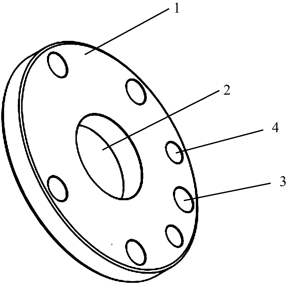
[0036] There is a partition 1 between the two cylinders, such as figure 1 As shown, the separator 1 is disc-shaped. A first through hole 2 is provided on the partition 1 for the crankshaft to pass through. In addition, installation through holes are provided on the partition 1, including five second through holes 3 with a diameter of 105 mm and two third through holes 4 with a diameter of 8 mm.

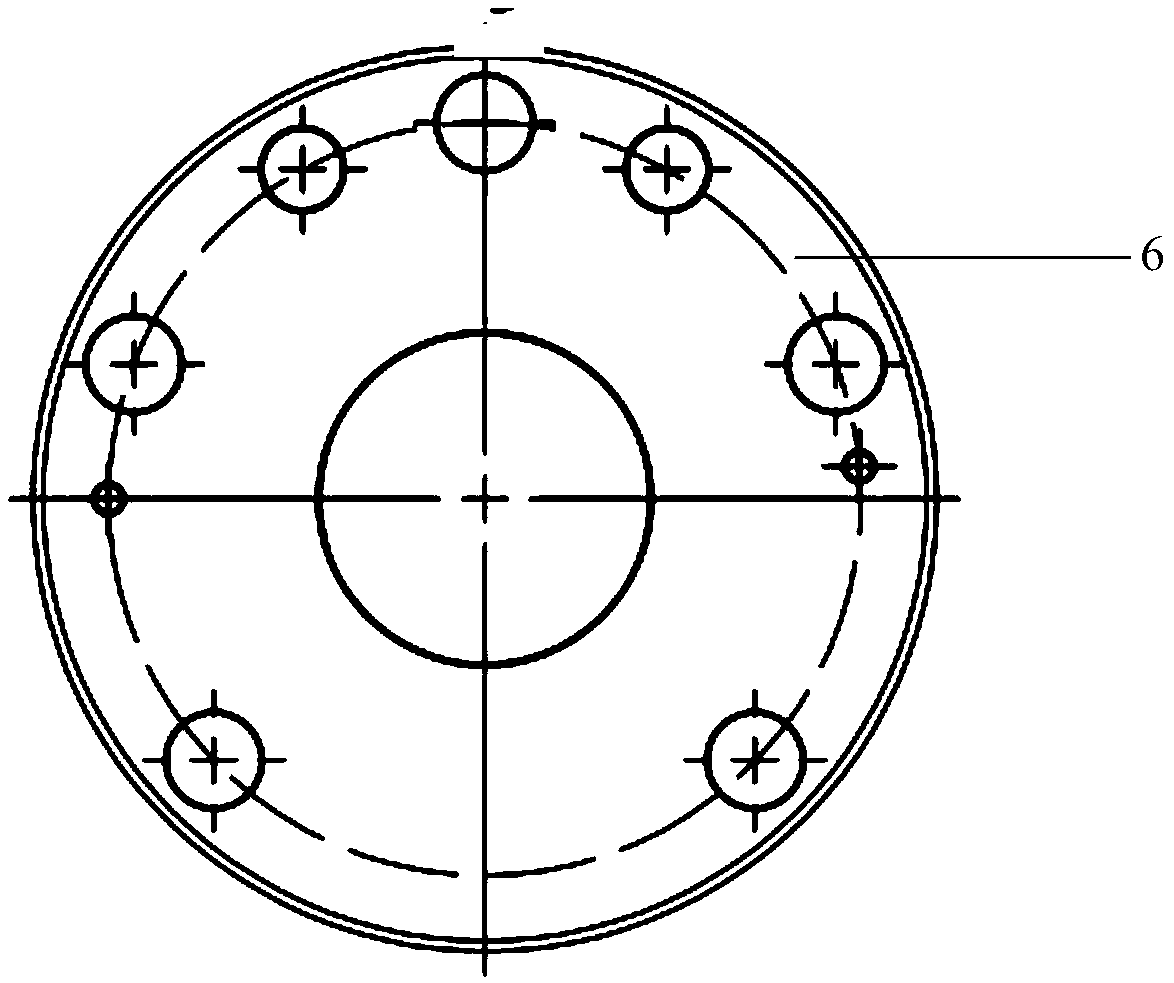
[0037] In this embodiment, steel plates are used to manufacture the above-mentioned separators 1 by laser cutting, as figure 2 As shown, the details are as follows:

[0038] Utilizing formed steel plates 6, according to figure 1 The shape and size of the required separator are obtained by laser cutting with a first through hole 2, five second through holes 3, and two third through holes 4. figure 1 separator...

Embodiment 2

[0040] In this embodiment, the structure of the partition in the double-cylinder compressor is exactly the same as that in Embodiment 1.

[0041] In this embodiment, steel plates are used to manufacture the above partitions through high-pressure water jet cutting process, as follows:

[0042] Utilize the formed steel plate, according to the shape and size of the required partition, cut a cut piece with a first through hole 2, five second through holes 3, and two third through holes 4 by high-pressure water jet cutting, That is, get as figure 1 separator shown.

Embodiment 3

[0044] In this embodiment, the two-cylinder compressor includes two sliding vanes, two pistons, two cylinders, one crankshaft, one main bearing, and one auxiliary bearing.

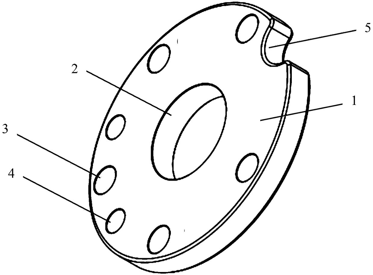
[0045] There is a partition 1 between the two cylinders, such as image 3 As shown, the separator 1 is in the shape of a disk, and the edge is in a concave structure 5 . A first through hole 2 is provided on the partition plate 1 for the crankshaft to pass through. In addition, installation through holes are provided on the partition 1 , including five second through holes 3 with a diameter of 10.5 mm and two third through holes 4 with a diameter of 8 mm.

[0046] In this embodiment, steel plates are used to manufacture the above-mentioned separator 1 by high-pressure water jet cutting, as Figure 4 As shown, the details are as follows:

[0047] Utilizing formed steel plates 6, according to image 3 The shape and size of the required baffle are cut by high-pressure water jets with concave structure 5, ...


PUM


Abstract

The invention provides a manufacturing method of a partition plate in a multi-cylinder compressor. The partition plate is located between two adjacent cylinders, and is provided with a through hole Aused for allowing a crank shaft to penetrate through. The partition plate is manufactured of steel through a cutting technology. According to the manufacturing method, the technology is simple and effective, the cost is low, environment protection is achieved, pollution is free, and the integral strength, hardness and dimension precision of the partition plate can be guaranteed. Particularly, whenthe steel is cut by a laser cutting technology, or the steel is cut by a high-pressure water jet cutting technology, the manufacturing efficiency and manufacturing precision can be further improved.

Description

technical field [0001] The invention relates to the technical field of compressors, in particular to a method for manufacturing a partition in a multi-cylinder compressor. Background technique [0002] Rotary refrigeration compressors are widely used in air conditioners such as households because of their high refrigeration efficiency, compact structure, small size, and light weight. [0003] The compression assembly is an important part of the rotary refrigeration compressor, mainly including the cylinder, piston, vane, crankshaft, main bearing and auxiliary bearing. The multi-cylinder compressor includes at least two cylinders, each cylinder has a compression chamber, a partition is arranged between two adjacent cylinders, and a through hole is formed on the partition to allow the crankshaft to pass through. [0004] At present, the separator is generally made by a casting process or a powder metallurgy process. [0005] The casting process is generally a process in whic...

Claims


Application Information

Patent Timeline
Patent Type & Authority Applications(China)
IPC IPC(8): F04C29/00F04C23/00
CPCF04C23/00F04C29/00F04C2240/80
Inventor 庄希平林国富郑贺
Owner NINGBO YONGWEI GROUP
Why Eureka
Try Eureka