Laser shock peening method based on liquid nitrogen restraint layer

A technology of laser shock strengthening and confinement layer, which is applied in the field of laser shock strengthening, can solve the problems of uneven liquid nitrogen confinement layer on the surface of the workpiece, poor confinement effect, unsatisfactory laser shock finishing effect, etc., and is beneficial to industrial production application, Simple structure and improved fatigue life

Inactive Publication Date: 2019-01-11
HUAZHONG UNIV OF SCI & TECH
View PDF4 Cites 9 Cited by
  • Summary
  • Abstract
  • Description
  • Claims
  • Application Information

AI Technical Summary

Problems solved by technology

Patent CN200510094810.9 discloses a method and device for pressurizing a new type of water-constrained layer based on laser shock technology, and proposes a laser shock method and device based on a relatively uniform thickness of flowing water-constrained layer. In other words, the liquid nitrogen confinement layer can significantly improve the lattice distortion and dislocation density in the processed workpiece, thereby greatly improving the fatigue life of the workpiece and prolonging the service life of the workpiece; patent CN201410492392.8 discloses a method based on air laminar flow The laser shock wave pressure confinement method and device, using the air laminar flow formed by the temperature difference to constrain the laser-induced shock wave pressure, can achieve a better confinement effect under the air pressure of 0.7-2.5MPa, but it is only suitable for high-temperature laser shock occasions. It has obvious limitations in low-temperature shock, and the laser shock technology based on liquid nitrogen confinement layer can solve this problem well; the patent CN105063284A proposes a deep laser shock technology with high light transmittance suitable for cryogenic laser shock technology. Cold laser impact head and laser shock system, but use static liquid nitrogen as the confinement layer. During the laser shock process, due to the high energy, the liquid nitrogen rapidly heats up and gasifies, which makes the liquid nitrogen confinement layer on the surface of the workpiece uneven, resulting in poor confinement effect. The effect of laser shock finishing is not ideal, and it is not as good as the confinement effect of flowing liquid such as running water or K9 optical glass

Method used


Image

  • Laser shock peening method based on liquid nitrogen restraint layer
  • Laser shock peening method based on liquid nitrogen restraint layer

Examples


Embodiment Construction

[0023] In order to make the object, technical solution and advantages of the present invention clearer, the present invention will be further described in detail below in conjunction with the accompanying drawings and embodiments. It should be understood that the specific embodiments described here are only used to explain the present invention, not to limit the present invention. In addition, the technical features involved in the various embodiments of the present invention described below can be combined with each other as long as they do not constitute a conflict with each other.

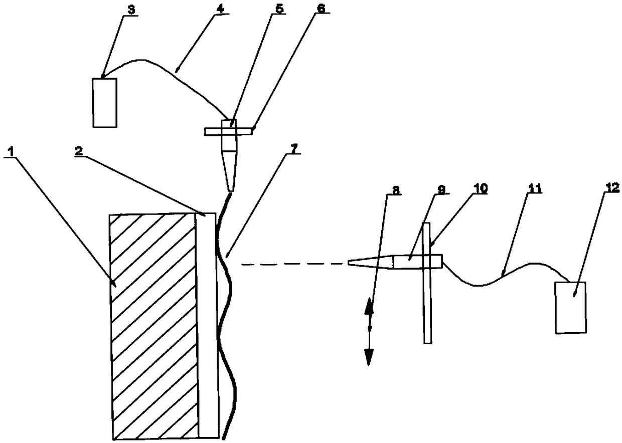
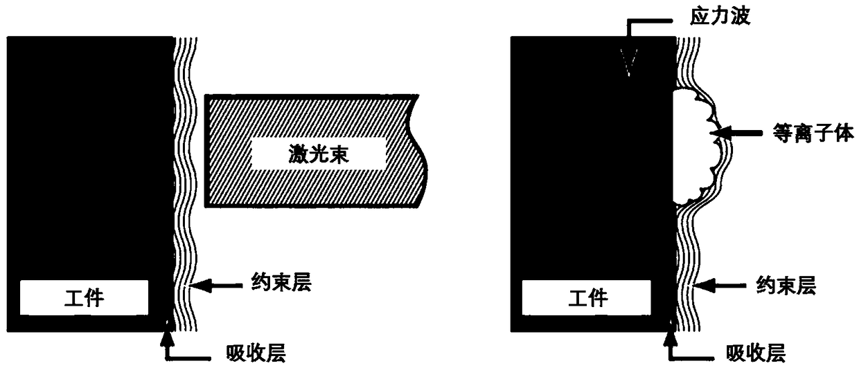
[0024] figure 1 is a structural schematic diagram of a laser shock peening system constructed according to a preferred embodiment of the present invention, as figure 1 As shown, the liquid nitrogen storage tank 3 is connected to the liquid nitrogen nozzle 5 through the pipeline 4, the nozzle 5 is fixed on the variable position type liquid nitrogen support frame 6, the absorbing layer 2 is evenl...


PUM

PropertyMeasurementUnit
thicknessaaaaaaaaaa
thicknessaaaaaaaaaa

Abstract

The invention belongs to the laser shock peening field and discloses a laser shock peening method based on a liquid nitrogen restraint layer. The method comprises the following steps: (a) cooling thesurface of a to-be-machined workpiece, coating the surface of the to-be-machined workpiece with a material for absorbing laser energy so as to form an absorbing layer, fixing the to-be-machined workpiece, and spraying liquid nitrogen to the absorbing layer to form a flowing liquid nitrogen layer, namely the restraint layer; and (b) irradiating the surface of the to-be-machined workpiece with laser. The laser penetrates through the restraint layer and arrives at the absorbing layer, the absorbing layer absorbs plasma produced through the gasification of the laser energy, is heated and expandedalong the continuous absorbing of the laser energy and finally explodes to generate high-pressure shock waves towards the inside of the to-be-machined workpiece to enable the to-be-machined workpieceto generate plastic deformation, so that then dislocation density and compactness of crystalline grains in the to-be-machined workpiece are increased, and the crystal lattice size is decreased. According to the laser shock peening method, the dislocation density of the crystalline grains is increased, the crystal lattice size is decreased, the fatigue resistance of the surfaces of blades of an aviation engine is increased, and the service life of the aviation engine is prolonged.

Description

technical field [0001] The invention belongs to the field of laser shock strengthening, and more specifically relates to a laser shock strengthening method based on a liquid nitrogen constrained layer. Background technique [0002] Laser shock peening is a new technology for material modification using laser-induced shock wave pressure, and it is a green manufacturing technology that is expected to replace traditional mechanical shot peening modification. On this basis, by laser shocking the metal surface under a certain temperature effect, higher dislocation density and dislocation entanglement can be obtained, accompanied by the appearance of dynamic strain aging and dynamic precipitation. These characteristics determine that laser shock under a certain temperature effect can achieve a better surface strengthening effect than normal temperature laser shock. [0003] In the manufacturing process of aero-engine blades, laser shock is the key and core process step in the who...

Claims


Application Information

Patent Timeline
Patent Type & Authority Applications(China)
IPC IPC(8): C21D10/00
CPCC21D10/005
Inventor 林栋肖峻峰罗优明许剑锋
Owner HUAZHONG UNIV OF SCI & TECH
Why Eureka
Try Eureka