Single-feed circularly polarized dielectric resonator antenna

A dielectric resonator, circularly polarized technology, applied in the field of antennas, can solve the problems of complex structure, low gain, narrow axial ratio bandwidth, etc., and achieve the effect of high radiation gain

Active Publication Date: 2019-01-11
NANTONG UNIVERSITY
View PDF2 Cites 15 Cited by
  • Summary
  • Abstract
  • Description
  • Claims
  • Application Information

AI Technical Summary

Problems solved by technology

Among them, the DRA with multiple feed points has a wider axial ratio bandwidth, but it needs to use an additional feed network, and the structure is relatively complex
The DRA with a single feed point has a simple structure, but usually has a narrow axial ratio bandwidth. There are various technical means to expand its axial ratio bandwidth. For example, a special-shaped DR can be used, but this irregular-shaped antenna is not easy to process and manufacture. It is also difficult to analyze with traditional theories; enlarging the aspect ratio or aspect ratio of DR can also increase the axial ratio bandwidth, but the problem brought by this method is that the size of the antenna is increased; using improved feeding technology is also a It is an effective method to broaden the axial ratio bandwidth, but the dielectric material with low dielectric constant is often used in this type of design, resulting in lower gain

Method used


Image

  • Single-feed circularly polarized dielectric resonator antenna
  • Single-feed circularly polarized dielectric resonator antenna
  • Single-feed circularly polarized dielectric resonator antenna

Examples


Embodiment Construction

[0020] In order to facilitate the understanding of the present invention, the present invention will be described more fully below with reference to the relevant drawings. The drawings show typical embodiments of the invention. However, the present invention can be implemented in many different forms and is not limited to the embodiments described herein. On the contrary, the purpose of providing these embodiments is to make the disclosure of the present invention more thorough and comprehensive.

[0021] It should be noted that the terms "vertical", "horizontal" and similar expressions used herein are only for illustrative purposes. Unless otherwise defined, all technical and scientific terms used herein have the same meaning as commonly understood by those skilled in the technical field of the present invention. The terms used in the specification of the present invention herein are only for the purpose of describing specific embodiments, and are not intended to limit the pre...


PUM


Abstract

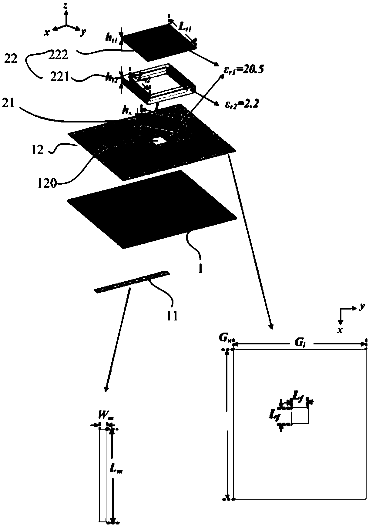
The invention discloses a single-feed circularly polarized dielectric resonator antenna, comprising a dielectric substrate, wherein a microstrip line is arranged on a lower surface of the dielectric substrate, a metal large-scale stratum is arranged on an upper surface of the dielectric substrate, and the metal large-scale stratum is provided with a coupling groove for coupling and feeding with the microstrip line; a top layer radiating element comprising a striped dielectric resonator and a hollow double-layer dielectric resonator; Wherein the double-layer dielectric resonator is arranged onthe metal large-scale formation and covers the coupling groove; a tape dielectric resonator is arranged on that metal large-scale formation, and in a hollow region located in the double layer dielectric resonator, wherein the strip dielectric resonator is formed by rotating a preset angle in a counterclockwise direction from a top-down view angle about a center point of the strip dielectric resonator in a horizontal plane from a direction perpendicular to a microstrip line so as to realize conversion from a linearly polarized wave to a circularly polarized wave. The antenna of the invention has high gain, low profile and wide operating bandwidth.

Description

Technical field [0001] The present invention relates to the field of antennas, in particular to a single-fed circularly polarized dielectric resonator antenna. Background technique [0002] Circularly polarized dielectric resonator antenna (Dielectric Resonator Antenna, DRA) has the advantages of high radiation efficiency, flexible design, resistance to rain and fog interference and multipath effects, and has broad application prospects in satellite communications, navigation, and mobile communications. [0003] In recent years, antenna researchers at home and abroad have invested a lot of research on circularly polarized dielectric resonator antennas. Generally, there are two feeding schemes for generating circularly polarized waves, namely single-feed point and multi-feed point technology. Among them, the DRA with multiple feed points has a wider axial ratio bandwidth, but an additional feed network is required, and the structure is relatively complicated. The DRA with a single...

Claims


Application Information

Patent Timeline
Patent Type & Authority Applications(China)
IPC IPC(8): H01Q1/36H01Q1/48H01Q1/50
CPCH01Q1/36H01Q1/48H01Q1/50
Inventor 杨汶汶董星妤陈建新
Owner NANTONG UNIVERSITY
Why Eureka
Try Eureka