Microwave ignition system and method capable of being applied to engine combustor

A microwave ignition and combustion chamber technology, applied in engine ignition, engine components, machines/engines, etc., can solve problems such as wasting fuel, low energy efficiency, and low overall efficiency

Inactive Publication Date: 2019-01-15
深圳市奥谱太赫兹技术研究院
View PDF9 Cites 1 Cited by
  • Summary
  • Abstract
  • Description
  • Claims
  • Application Information

AI Technical Summary

Problems solved by technology

During this time, the work done by localized combustion resists the kinetic energy of the engine, resulting in wasted energy and overall low efficiency (wasting five to ten percent of energy)
In fact the energy efficiency of an engine with spark ignition is indeed lower, only about 30%, wasting precious fuel
(2) Pollution to the environment

Method used


Image

  • Microwave ignition system and method capable of being applied to engine combustor
  • Microwave ignition system and method capable of being applied to engine combustor
  • Microwave ignition system and method capable of being applied to engine combustor

Examples


Embodiment 1

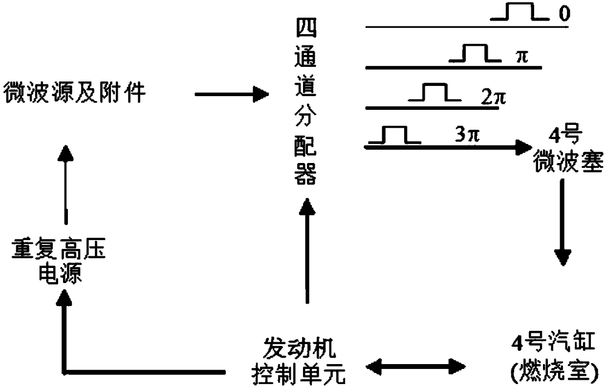
[0034] Such as Figure 1-9As shown, the present invention provides a microwave ignition system and method applicable to engine combustion chambers, including an engine control unit, a microwave source, a repetitive high-voltage power supply, a microwave distributor and a combustion chamber, and the combustion chamber is provided with several, The microwave source is respectively communicated with several combustion chambers through a microwave distributor, and a microwave plug is installed in each distribution channel of the microwave distributor, and the engine control unit is respectively connected with the repeated high-voltage power supply, the microwave distributor and the burner control connected, the repetitive high-voltage power supply is electrically connected to the microwave source.

[0035] Figure 1 Composition diagram for the entire ignition system. First select a microwave source that can output the appropriate frequency, bandwidth, power, and pulse length. T...


PUM


Abstract

The invention discloses a microwave ignition system capable of being applied to an engine combustor. The microwave ignition system comprises an engine control unit, a microwave source, a microwave distributor and combustors. The microwave source communicates with the multiple combustors through the microwave distributor. A microwave plug is installed in each distribution channel of the microwave distributor. The engine control unit is in control connection with a repeated high voltage power supply, the microwave distributor and a burner. The repeated high voltage power supply is electrically connected with the microwave source. In the microwave ignition system, the microwave frequency is consistent with a certain electromagnetism eigenfrequency of the combustors, and thus microwave energycan be coupled into the combustors in a resonance mode. When an engine works, microwave energy of a certain frequency is coupled into an air cylinder of the engine, and oil-gas mixed gas in the enginecombustor is ignited at an appropriate moment. After ignition, residual microwave energy interacts with plasma generated by burning in the combustor, thus overall burning in the combustor is achievedextremely quickly, more complete burning of the oil-gas mixture is facilitated, and tail gas discharge is reduced.

Description

technical field [0001] The invention relates to a microwave ignition system and method, in particular to a microwave ignition system and method applicable to engine combustion chambers, and belongs to the technical field of engines. Background technique [0002] A fundamental component in an engine is the combustion chamber that converts the chemical energy of the fuel into mechanical energy. For a turbine engine, such as a gas turbine aircraft engine, its typical combustion chamber is in the shape of a barrel with one end open or partially or entirely composed of an annular shell. In fact, an engine can have multiple barrel combustors, or a single annular combustor. Engines can also have pre-combustion chambers and after-combustion chambers. Other engines include: rotary engines and reciprocating piston engines for automobiles; rocket engines; ramjet engines and pulse air jet engines. [0003] Ignition of fuel in the combustion chamber depends on several factors: oil and...

Claims


Application Information

Patent Timeline
IPC IPC(8): F02P23/04
CPCF02P23/045
Inventor 何文华
Owner 深圳市奥谱太赫兹技术研究院
Why Eureka
Try Eureka