Shield mud treatment system and shield mud treatment method

A treatment system and mud technology, applied in sludge treatment, water/sludge/sewage treatment, sedimentation treatment, etc., can solve the problems of small footprint and failure to meet environmental protection requirements, achieve simple structure, reduce costs, and improve The effect of processing efficiency

Inactive Publication Date: 2019-02-01
CHINA RAILWAY 14TH BUREAU GRP LARGE SHIELD ENG CO LTD
View PDF9 Cites 5 Cited by
  • Summary
  • Abstract
  • Description
  • Claims
  • Application Information

AI Technical Summary

Problems solved by technology

The efficiency of this method is higher than that of sedimentation and separation, and it occupies a small area. However, due to the need to add a large amount of lime to carry out effective press filtration, the pH of the press-filtered water and mud cake is 11-12 or even higher, far exceeding the current national emission standards. Cannot meet environmental protection requirements

Method used


Image

  • Shield mud treatment system and shield mud treatment method
  • Shield mud treatment system and shield mud treatment method

Examples


Embodiment 1

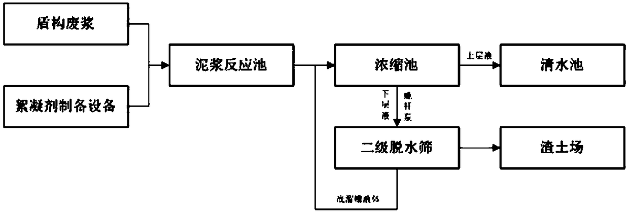
[0031] A shield mud handling system such as figure 1 As shown, it includes shield machine waste slurry extraction pump, automatic flocculant liquid preparation and dosing system, mud reaction tank, thickening tank, clear water tank, secondary dewatering screen, slurry outlet of shield machine waste slurry extraction pump, fully automatic The drug outlets of the flocculant liquid preparation and dosing system are all connected to the mud reaction tank, the output end of the mud reaction tank is connected to the thickening tank, the overflow port of the thickening tank is connected to the clear water tank, and the bottom flow outlet of the thickening tank is connected with the screw pump. The secondary dewatering screen is connected, the bottom flow reflux tank of the secondary dewatering screen is connected with the concentration tank, and the slag outlet of the secondary dehydrating screen leads to the muck field.

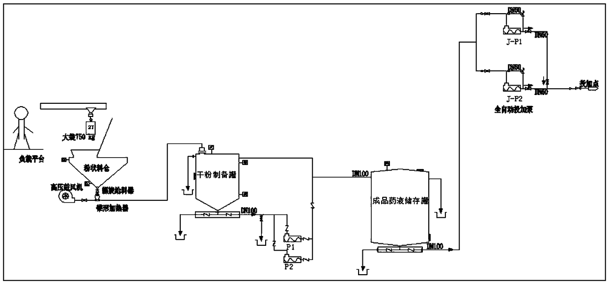
[0032] The automatic flocculant liquid preparation and dosing...

Embodiment 2

[0038] A shield mud processing method, comprising the following steps:

[0039] Step 1: The fully automatic flocculant solution preparation and dosing system uses polyacrylamide flocculant dry powder to prepare a flocculant solution with a concentration of 1‰-3‰, and the shield machine waste slurry extraction pump extracts the shield machine waste slurry from the shield construction site ;

[0040] Step 2: Mix and pump the flocculant solution and waste shield slurry to the mud reaction tank;

[0041] Step 3: Stir the mixed solution in the mud reaction tank and then pump it to the concentration tank, where the mixed solution is concentrated;

[0042] Step 4: The supernatant of the concentration tank overflows to the clear water tank, and the bottom flow layer is discharged to the secondary dewatering screen through the rotation of the rake;

[0043] Step 5: The secondary dehydration screen is used for dehydration and slag removal. The secondary dehydration screen includes two...


PUM


Abstract

The invention provides a shield mud treatment system, which comprises a shield waste slurry suction pump, a fully-automatic flocculant preparation and feeding system, a mud reaction pool, a concentration pool, a clear water pool and a two-stage dewatering sieve, wherein the slurry outlet of the shield waste slurry suction pump and the agent outlet of the fully-automatic flocculant preparation andfeeding system are respectively connected to the mud reaction pool, the output end of the mud reaction pool is connected to the concentration pool, the overflow port of the concentration pool is connected to the clear water pool, the underflow outlet of the concentration pool is connected to the two-stage dewatering sieve through a screw pump, the underflow reflux groove of the two-stage dewatering sieve is connected to the concentration pool, and the residue outlet of the two-stage dewatering sieve is communicated to a residue soil field. According to the present invention, the flocculant solution is automatically prepared, and is mixed with the waste slurry, and the supernatant is discharged and the underflow is subjected to dewatering residue discharge after the concentration treatment,such that the cost can be effectively reduced, the system and the method are less affected by the weather, and the shield waste slurry treatment efficiency is improved.

Description

technical field [0001] The invention belongs to the technical field of shield machine waste slurry treatment, in particular to a shield machine mud treatment system and a treatment method. Background technique [0002] my country's current urbanization process has entered the stage of accelerated urban development, and the rapid increase in urban population has led to a sharp increase in the total amount of traffic; this requires the expansion of the service scope and capabilities of the urban passenger transport system. As a result, more and more underground basic transport The facilities need to be developed and constructed, and a large amount of mud will be produced when the mud-water balance shield method is used for tunneling in subway tunnels. Since construction sites in urban areas are greatly restricted by various factors such as urban traffic, buildings, land acquisition and demolition, and environmental protection, construction sites are generally extremely compact....

Claims


Application Information

Patent Timeline
Patent Type & Authority Applications(China)
IPC IPC(8): C02F9/04C02F11/121C02F11/147
CPCC02F1/56C02F11/121C02F2001/007
Inventor 刘德龙周庆合王华伟吴瑞涛王磊王硕
Owner CHINA RAILWAY 14TH BUREAU GRP LARGE SHIELD ENG CO LTD
Why Eureka
Try Eureka