
Isothermal compressed air energy storage system and high-efficiency power generation method

A compressed air energy storage and isothermal technology, applied in the direction of reducing greenhouse gases, system integration technology, neural learning methods, etc., can solve the problems of heat resource loss, environmental pollution, low power generation efficiency, etc.

Inactive Publication Date: 2019-02-15
NORTH CHINA ELECTRIC POWER UNIV (BAODING) +2
View PDF5 Cites 3 Cited by
  • Summary
  • Abstract
  • Description
  • Claims
  • Application Information

AI Technical Summary

Problems solved by technology

When the system is storing energy, the compressor works under variable working conditions, and the compression efficiency is low; when generating electricity, fossil fuels need to be burned, causing serious loss of heat resources and polluting the environment
[0004] Therefore, there is an urgent need for a new compressed air energy storage system to solve the shortcomings of low power generation efficiency and insufficient utilization of thermal resources in the prior art compressed air energy storage system, and to achieve the effect of efficient energy storage and power generation of the system

Method used


Image

  • Isothermal compressed air energy storage system and high-efficiency power generation method
  • Isothermal compressed air energy storage system and high-efficiency power generation method
  • Isothermal compressed air energy storage system and high-efficiency power generation method

Examples


Embodiment Construction

[0086] Below in conjunction with accompanying drawing, the embodiment of the present invention is described in detail;

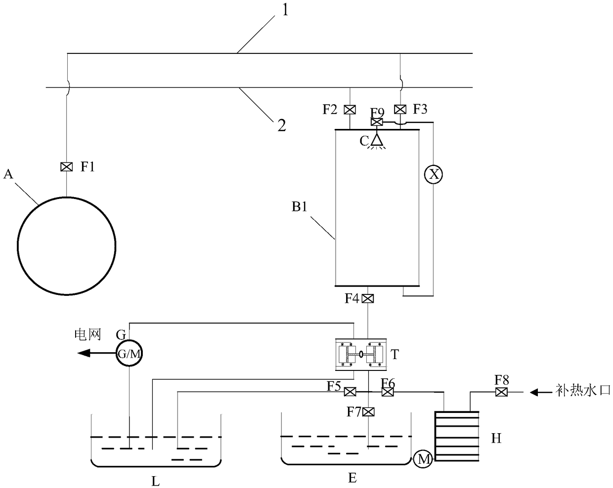
[0087] Such as figure 1 The illustrated embodiment of the present invention includes: G pumped storage power generation unit, D hydraulic transmission unit, B1 liquid piston, C spray equipment, A gas storage unit, L low-temperature water pool, H solar supplementary heater, E hot water storage tank , high-pressure gas pipeline 1, low-pressure gas pipeline 2, X spray drive device, Y hydraulic drive device and F1-F9 valves; the top of B1 liquid piston respectively passes through F2 valve, F3 valve and low-pressure gas pipeline 2, high-pressure gas pipeline 1 is connected, and the top of the B1 liquid piston is equipped with C spraying equipment; the low-pressure gas pipeline 2 is connected to the compressor; one end of the high-pressure gas pipeline 1 is connected to the compressor, and the other end of the high-pressure gas pipeline 1 is connected to the A gas...


PUM


Abstract

The invention discloses an isothermal compressed air energy storage system and a high-efficiency power generation method, and belongs to the field of large-capacity energy storage. The top end of a liquid piston in the energy storage system is connected to a low pressure gas pipeline and a high pressure gas pipeline through F2 and F3 valves separately; the low pressure gas pipeline is connected toa compressor; one end of the high pressure gas pipeline is connected to the compressor and the other end of the high pressure gas pipeline is connected to a gas storage unit through F1; an only waterinlet below the liquid piston is connected to a liquid outlet on the secondary side of a hydraulic transmission unit through F4, the other liquid outlet on the secondary side of the hydraulic transmission unit is connected to a four-way, and the other three outlets of the four-way are separately connected with a low temperature pool, the top end of a solar heat supplement machine and a hot waterstorage tank; and the bottom end of the solar heat supplement machine is connected to the hot water storage tank through a hydraulic driving device, and the top end of the solar heat supplement machine is connected to a hot water supply port through F8. The isothermal compressed air energy storage system and the high-efficiency power generation method utilize a temperature prediction and liquid temperature control algorithm, and configure a liquid spray device to realize isothermal compression or expansion of the system.

Description

technical field [0001] The invention belongs to the technical field of large-capacity energy storage, and in particular relates to an isothermal compressed air energy storage system and a high-efficiency power generation method. Background technique [0002] The research and development of energy storage technology is of great significance to promote the renewable energy industry. Large-scale energy storage can achieve a high proportion of renewable energy such as wind energy and photovoltaics connected to the grid. The wind farm is equipped with a certain capacity of compressed air energy storage equipment, which can smooth or even move the wind energy output, so that the characteristics of the wind power generation system are close to those of synchronous generator systems such as thermal power generation, and ensure the stable, reliable and safe operation of the power system. [0003] At present, large-capacity compressed air energy storage power stations generally adopt...

Claims


Application Information

Patent Timeline
IPC IPC(8): F04B35/00F04B41/02F04B31/00F02G1/043F02G1/055G06N3/08
CPCF02G1/0435F02G1/055F04B31/00F04B35/00F04B41/02G06N3/08Y02E40/70Y02E60/16Y02E70/30Y04S10/50
Inventor 姜彤韩宗耀
Owner NORTH CHINA ELECTRIC POWER UNIV (BAODING)
Learn More