Strain sensor, structure monitoring system and manufacturing method

A strain sensor and structure monitoring technology, applied in the direction of electric/magnetic solid deformation measurement, instrument, measurement force, etc., can solve the problems of real-time health monitoring, small fiber deformation and expansion rate, fiber breakage failure, etc., to achieve small occupied space, A wide range of applications, the effect of reducing the weight of the structure

Inactive Publication Date: 2019-02-15
CHINA ACAD OF LAUNCH VEHICLE TECH
View PDF5 Cites 5 Cited by
  • Summary
  • Abstract
  • Description
  • Claims
  • Application Information

AI Technical Summary

Problems solved by technology

However, in the application of composite material structure health monitoring, for composite material parts that require secondary bonding, it is necessary to manually bond the optical fiber to the inner surface of the composite material structure, and then enter the autoclave for secondary curing or secondary bonding , it is prone to the problem of fiber breakage and failure
This is due to the fact that the deformation and expansion rate of the optical fiber is smaller than that of the composite material, so this method is not suitable for composite material structures that need to be cured after the monitoring network is laid.
In the new generation of aerospace vehicle structural systems, the application of composite materials is becoming more and more extensive, and some even reach more than 80% of the amount, and the overall curing, co-bonding and secondary bonding processes are usually used, which are complicated and expensive.
Therefore, it is urgent to develop a new monitoring method that can adapt to the structure of complex composite components to solve the problem of real-time health monitoring of advanced aerospace vehicle composite structures.

Method used


Image

  • Strain sensor, structure monitoring system and manufacturing method
  • Strain sensor, structure monitoring system and manufacturing method
  • Strain sensor, structure monitoring system and manufacturing method

Examples


Embodiment 1

[0056] Taking an all-composite material rudder wing of a certain spacecraft as an example, the specific implementation steps of the technical solution of the present invention are described.

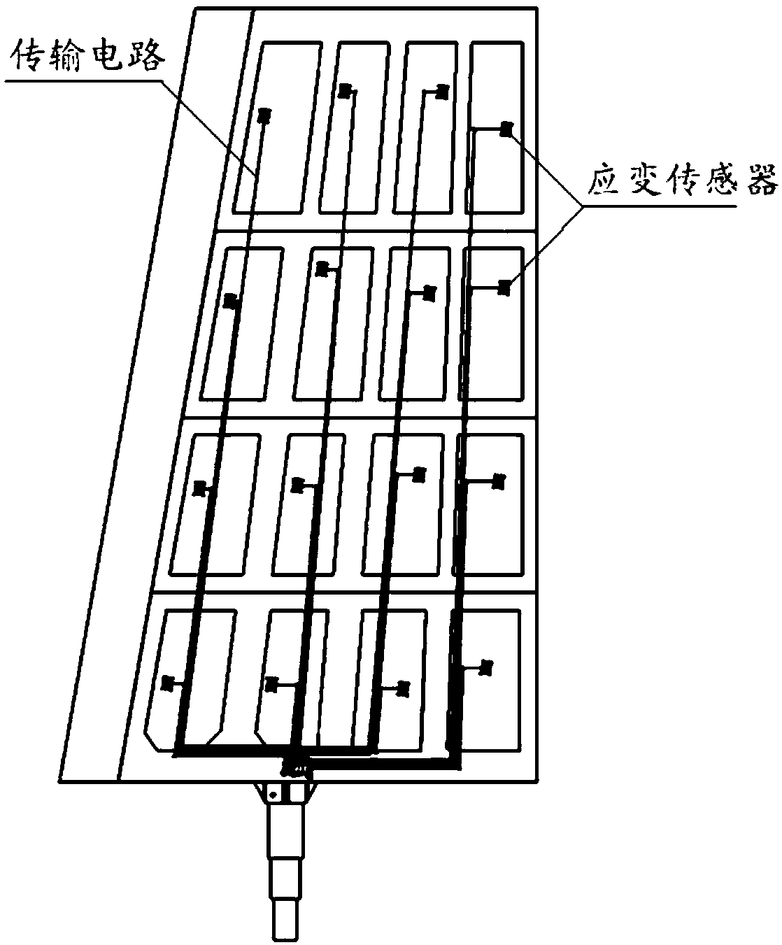
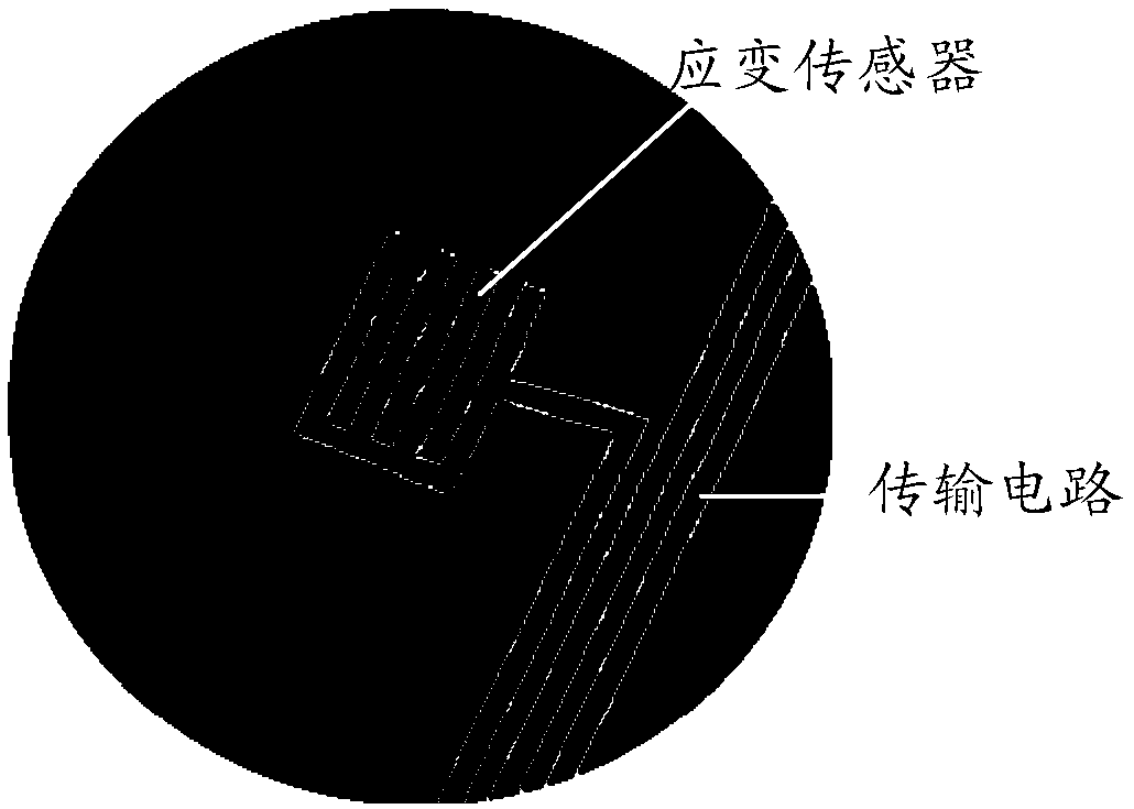
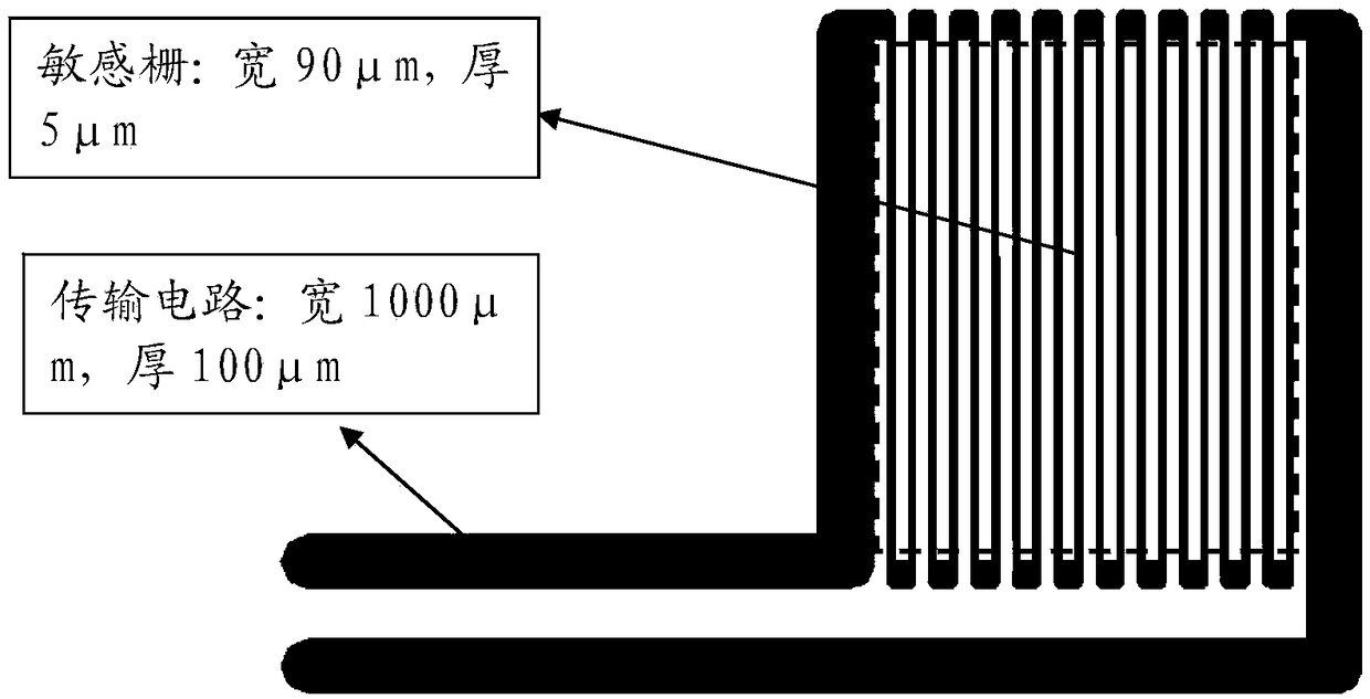
[0057] (1) Design the structure monitoring circuit according to the structure scheme of the rudder wing. First, determine the monitoring position of the strain sensor and the direction of the transmission circuit, such as figure 1 shown. Then design the direction of the sensitive grid of the strain sensor of the structure monitoring circuit and the size of the strain sensor, such as figure 2 shown. The longitudinal direction of the sensitive grid of the strain sensor should be consistent with the local maximum deformation direction of the structure, and the maximum deformation direction can be determined by the finite element simulation results. Then design the length, width and thickness of the strain sensor and the transmission circuit. During the design, it is necessary to ensure ...


PUM

PropertyMeasurementUnit
thicknessaaaaaaaaaa
electrical resistivityaaaaaaaaaa

Abstract

The invention relates to a strain sensor, a structure monitoring system and a manufacturing method. The method comprises: directly printing nano metal slurry on a surface of a structure based on a 3Dprinting technique; and solidifying to form a conductive trace for monitoring structural strain. The line has a width as low as tens of microns, a thickness as low as several microns and a small space, can be printed on composite bonding areas with minimal impact on the quality of the bond. The strain sensor, the structure monitoring system and the manufacturing method can be applied to health monitoring of large and complex composite structures. The conductive trace of the invention can realize the sensing of the structural strain and information transmission function through reasonable design, thereby realizing the safety monitoring and evaluation for the structure in total life cycle, and providing the necessary guarantee for the reuse of future advanced aircraft.

Description

technical field [0001] The invention relates to a strain sensor, a structure detection system and a manufacturing method, and belongs to the technical field of composite material structure health monitoring for aerospace vehicles. Background technique [0002] The new generation of advanced aerospace vehicles has the characteristics of long-term on-orbit and multiple uses, which poses challenges to the design, testing, maintenance and status monitoring of traditional structural systems. In order to evaluate the reliability of the aircraft structural system throughout its life cycle, it is necessary to carry out real-time health monitoring of important parts of the structural system. [0003] In order to achieve the goal of lightweight, advanced aerospace vehicles are increasingly using advanced carbon fiber reinforced resin matrix composites to manufacture important components such as cabin skin panels, grille shells, and rudder surfaces. However, the damage form of the com...

Claims


Application Information

Patent Timeline
Patent Type & Authority Applications(China)
IPC IPC(8): G01B7/16G01L1/22
CPCG01B7/16G01L1/22
Inventor 田甜代京王悦王福德梁晓康顾春辉许健吴迪李晓乐张帆李丹圆成磊陈亦冬唐青春彭扬
Owner CHINA ACAD OF LAUNCH VEHICLE TECH
Why Eureka
Try Eureka