M*N mechanical photoswitch

An optical switch and mechanical technology, applied in the field of optical communication, can solve problems such as difficult to realize optical or photoelectric integration, difficulty in mass production, and large volume of optical switches, and achieve the effects of reduced volume, low cost, and good repeatability

Pending Publication Date: 2019-02-22
NO 34 RES INST OF CHINA ELECTRONICS TECH GRP
View PDF7 Cites 0 Cited by
  • Summary
  • Abstract
  • Description
  • Claims
  • Application Information

AI Technical Summary

Problems solved by technology

The optical switch after cascaded M-level 1×N mechanical optical switches has a large overall volume, slow response time, and high cost. It is difficult to realize optical or optoelectronic integration with other devices, and it is not easy to mass produce. Existing M×N mechanical optical switches are difficult to popularize and apply

Method used


Image

  • M*N mechanical photoswitch
  • M*N mechanical photoswitch
  • M*N mechanical photoswitch

Examples


Embodiment 2

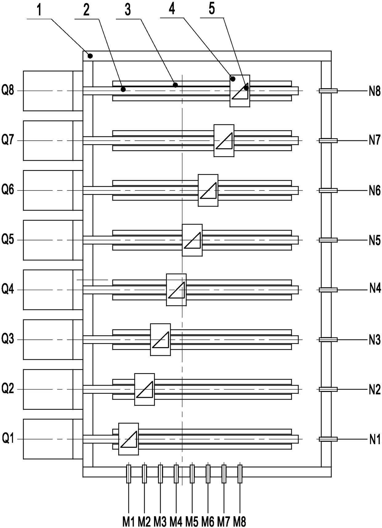
[0030] M=4, N=6 in the second embodiment of the M×N mechanical optical switch, which is a 4×6 mechanical optical switch, including a 4-core array collimator, a 6-core array collimator and a control center, and its bottom box The structure of 1 is the same as that of Embodiment 1. The 4-core array collimator is four identical collimators M arranged on the side of the bottom box A and in the same plane. 1 ,M 2 , M 3 , M M , their output optical paths are parallel to each other, and the intersection angle with the A side of the bottom box is α=80°. Similarly, the 6-core array collimator is 6 identical collimators N arranged on the side of the bottom box B in the same plane 1 ,N 2 …N 6 , their input optical paths are parallel to each other, and the intersection angle with the B side of the bottom box is also 80°. The optical path directions of the 4-core array collimator and the 6-core array collimator are in the same plane.

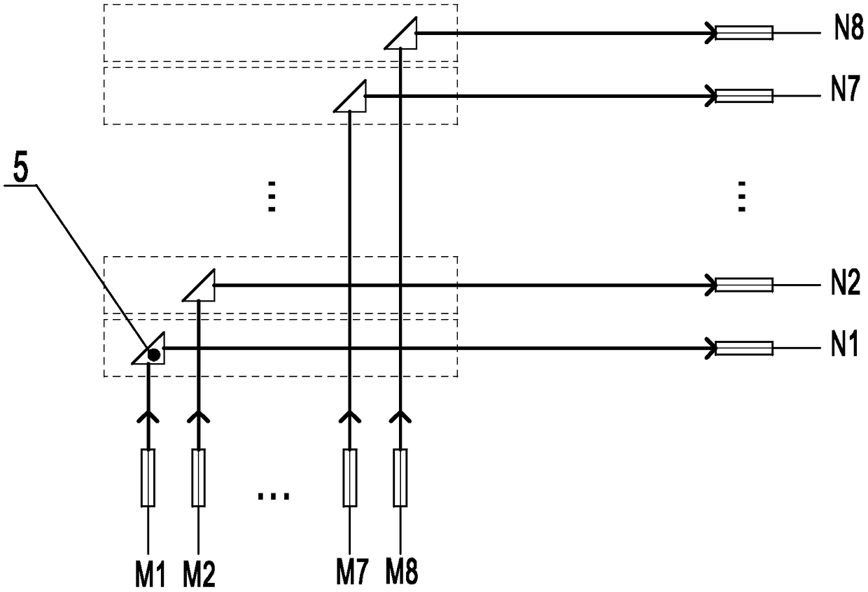
[0031] The light path in this example is as F...


PUM


Abstract

The invention relates to an M*N mechanical photoswitch, which comprises a bottom box, wherein an M-core array collimator is fixedly installed on the A side surface of the bottom box, M identical collimated output optical paths are parallel to each other, an N-core array collimator is fixedly installed on the B side surface adjacent to the A side surface, N is greater than or equal to M, and inputoptical paths of N identical collimators are parallel to one another; N motors are fixedly installed on the B' side surface of the bottom box, N guide rails are installed between the two side surfacesB and B', each guide rail is perpendicular to the side surfaces B and B', each guide rail is provided with a sliding block, and a reflector is fixedly installed on each sliding block to be opposite to the corresponding optical path; lead screws connected with motors are parallel to the guide rails, the lead screws are threaded in corresponding sliding block threaded holes, and the sliding blocksmove along the guide rails linearly when one motor starts to rotate the lead screws; electromagnetic switches of the motors are connected with a control center; and the reflectors are arranged in different positions, so that the M paths of input light can select N paths for output. The M*N mechanical photoswitch has the advantages of reduced size, low insertion loss, high isolation, low cost and good repeatability. The photoswitch has a high switching speed.

Description

technical field [0001] The invention belongs to the technical field of optical communication, in particular to an M×N mechanical optical switch used for optical signal exchange. Background technique [0002] Optical switch is an optical passive device that realizes the on-off of optical signal and the change of optical path. With the ultra-high development of optical communication transmission network technology, the performance of the original optical switch technology has been continuously improved, and various functional types of optical switches have been emerging. According to the current production process, it is mainly divided into two categories, one is the M×N optical switch of the micro-electromechanical system (MEMS) process, and the other is the M×N mechanical optical switch. [0003] Mechanical optical switches have low insertion loss, high isolation, wavelength and polarization independent, strong anti-vibration test performance, and relatively mature producti...

Claims


Application Information

Patent Timeline
Patent Type & Authority Applications(China)
IPC IPC(8): G02B26/08
CPCG02B26/0816
Inventor 钟昌锦刘斌付益唐群植汤科
Owner NO 34 RES INST OF CHINA ELECTRONICS TECH GRP
Why Eureka
Try Eureka