Electrochemical scale removing device

A descaling, electrochemical technology, applied in chemical instruments and methods, descaling and water softening, water/sludge/sewage treatment, etc., to achieve the effect of extending the service period, reducing the risk of corrosion, and improving thermal efficiency

Pending Publication Date: 2019-03-01
DALIAN UNIV OF TECH
View PDF0 Cites 1 Cited by
  • Summary
  • Abstract
  • Description
  • Claims
  • Application Information

AI Technical Summary

Problems solved by technology

[0003] In order to solve the scaling problem caused by the precipitation of calcium and magnesium salts on the heat exchange surface of circulating water cooling equipment, the present invention designs an electrochemical descaling device by improving the cathode form, and avoids heat exchange by reducing the hardness and alkalinity in the circulating water system Surface fouling

Method used


Image

  • Electrochemical scale removing device
  • Electrochemical scale removing device
  • Electrochemical scale removing device

Examples


Embodiment 1

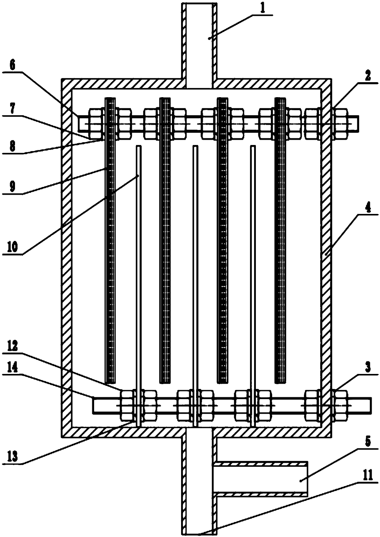
[0023] Such as figure 1 , an electrochemical descaling device, mainly includes a cathode 9 and an anode 10, the cathode 9 is nailed with 7 layers of stainless steel wire mesh, and the mesh numbers of the stainless steel wire mesh forming the cathode are 20 mesh, 12 mesh, 8 mesh, 50 mesh Mesh, 8 mesh, 12 mesh, 20 mesh. The cathode is fixed with stainless steel bolts 6 , nuts 7 and gaskets 8 , and the anode 10 is a DSA anode and fixed with titanium alloy bolts 14 , nuts 12 and gaskets 13 . The distance between adjacent cathodes and anodes is 3 mm. The equipment is placed vertically as a whole, and the water inlet 5 and the slag discharge port 11 are at the bottom of the equipment. During water intake, the pipeline valve at the lower part of the slag unloading port 11 is closed, and water flows in through the water inlet 5 and flows out through the water outlet 1 at the top.

[0024] Specifically, before the operation of the device, the positive pole of the DC constant current...

Embodiment 2

[0034] Such as figure 1 , an electrochemical descaling device, the spacing between adjacent cathodes and anodes is 5mm and 8mm, and the rest of the device parameters and operating conditions are the same as in Example 1. The relationship between the distance between adjacent cathodes and anodes and the performance of the descaler is shown in Table 2. It can be seen that the increase in the distance between adjacent cathodes and anodes does not significantly increase the descaling efficiency, but it significantly increases the descaling required. energy consumption. Therefore, the cathode and anode of the present invention are arranged alternately and closely to achieve the purpose of energy saving.

[0035] Table 2: Effect of spacing of adjacent cathodes and anodes on descaler performance

[0036]

Embodiment 3

[0038] Such as figure 1, an electrochemical descaling device, the multi-layer wire mesh constituting the cathode is selected from stainless steel mesh, copper mesh, nickel mesh and titanium mesh respectively, and the remaining device parameters and operating conditions are the same as in Example 1. The relationship between the material of the wire mesh that makes up the cathode and the performance of the descaler is shown in Table 3. It can be seen that the device uses wire mesh made of nickel, titanium and other materials to achieve better descaling performance, and the material used is stainless steel. And copper wire mesh has higher descaling rate and lower energy consumption.

[0039] Table 3: Effect of the wire mesh material making up the cathode on the performance of the descaler

[0040]

[0041]


PUM


Abstract

The invention discloses an electrochemical scale removing device, and relates to the field of industrial circulating water treatment and the like. The scale deposit problem of the heat exchange surface of existing circulating water cooling exchange equipment is solved. The electrochemical scale removing device comprises a power supply system and a working system, wherein the power supply system isa direct current source, and the working system is mainly formed by anodes and cathodes which are parallel, compact and alternately arranged. The anodes are non-sacrificial DSA anodes; the cathodes are formed by combining multiple layers of metal wire meshes with different mesh numbers, all composed meshes of the cathodes are connected and fixed through bolts, and a regeneration mode of the cathodes adopts ultrasonic cleaning. According to the electrochemical scale removing device, scale-forming ions in water are removed through the electrochemical scale removing device made from more-efficient and energy-saving cathodes; the electrochemical scale removing device works at the normal temperature, the scale removing efficiency is higher, a regeneration period of electrodes is longer, and energy dissipation is smaller.

Description

technical field [0001] The invention relates to the field of electrochemical water treatment systems, in particular to an electrochemical descaler. Background technique [0002] With the rapid development of oil refining, chemical industry and other industries, industrial water is becoming increasingly scarce. Circulating water cooling equipment is an important part of the refining circulating water system. However, with the extension of the operating time of the device, the scaling problem inside the heat exchanger is becoming more and more serious, which not only causes energy loss and waste of water resources, but also causes corrosion under the scale, leading to unplanned shutdown of production, loss of materials, and even explosions and other vicious ACCIDENT. Since the solubility of calcium carbonate decreases with the increase of temperature, when the circulating water flows through the heat exchange wall, when the temperature reaches the precipitation temperature o...

Claims


Application Information

Patent Timeline
Patent Type & Authority Applications(China)
IPC IPC(8): C02F5/00
CPCC02F5/00
Inventor 刘贵昌王立达孙文栾谨鑫李鑫浩
Owner DALIAN UNIV OF TECH
Why Eureka
Try Eureka