Vertical double-furnace-body chemical vapor deposition equipment

A chemical vapor deposition, dual-furnace technology, applied in gaseous chemical plating, metal material coating process, coating and other directions, can solve the problems of hidden dangers of equipment, residues, organic products not being effectively removed, etc., to improve production. Quality, the effect of improving production efficiency

Inactive Publication Date: 2019-03-19
SUZHOU HONGJIU AVIATION THERMAL MATERIALS TECH CO LTD
View PDF10 Cites 2 Cited by
  • Summary
  • Abstract
  • Description
  • Claims
  • Application Information

AI Technical Summary

Problems solved by technology

[0011] To sum up, the current chemical vapor deposition equipment is mainly a single-furnace reaction chamber structure. The reaction furnace and the tail gas treatment device are separated separately. The device is the main device, and the exhaust gas filtration and absorption efficiency is high, but the intermediate organic products in the exhaust gas have not been effectively removed, and a large amount of them will still remain in the pipeline, which will bring great danger to the equipment.

Method used


Image

  • Vertical double-furnace-body chemical vapor deposition equipment
  • Vertical double-furnace-body chemical vapor deposition equipment
  • Vertical double-furnace-body chemical vapor deposition equipment

Examples


Embodiment

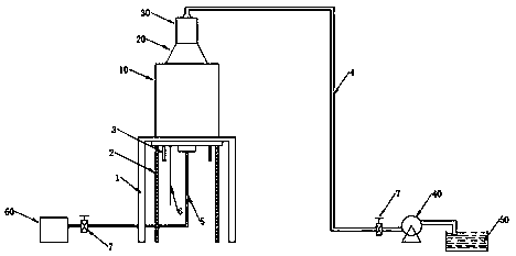
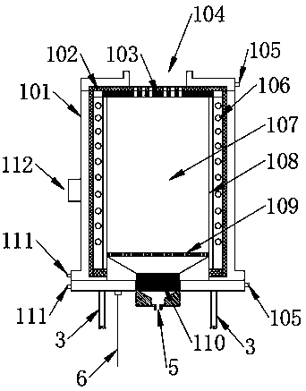
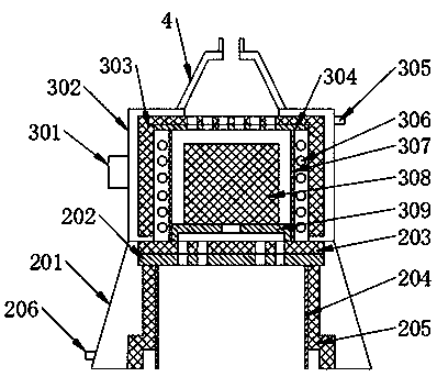
[0027] Vertical double furnace chemical vapor deposition equipment, such as figure 1 As shown, it includes support base 1, lifting system 2, lower furnace body support feet 3, exhaust pipe 4, inlet pipe 5, power cord 6, vacuum valve 7, lower furnace body 10, buffer furnace body 20, upper furnace body 30 , vacuum pump 40, filter tank 50, source gas system 60; the lower furnace body 10 is installed on the support base 1, the lower end of the lower furnace body 10 is connected to the lifting system 2, and the lower furnace body 10 is connected to the source gas system 60 through the intake pipe 5; buffer The body of furnace 20 is installed on the upper end of the lower body of furnace 10, and the upper body of furnace 30 is installed on the buffer body of furnace 20; the upper body of furnace 30 is connected with the vacuum pump 40 through the exhaust pipe 4, and the vacuum pump 40 is connected with the filter tank 50 through the exhaust pipe 4; The buffer furnace body 20 is used...


PUM

PropertyMeasurementUnit
diameteraaaaaaaaaa
heightaaaaaaaaaa
diameteraaaaaaaaaa

Abstract

The invention relates to vertical double-furnace-body chemical vapor deposition equipment. The vertical double-furnace-body chemical vapor deposition equipment is characterized that a support base, alifting system, a lower furnace body, a buffer system, an upper furnace body, a source gas system, a gas inlet pipe, a vacuum valve, a gas exhaust pipe, a vacuum pump and a filter tank are included. The lower furnace body is installed on the support base, the lower end of the lower furnace body is connected with the lifting system, and the lower furnace body is connected with the source gas systemthrough the gas inlet pipe. The buffer system is installed at the upper end of the lower furnace body, and the upper furnace body is installed above the buffer system. The upper furnace body is connected with the vacuum pump through the gas exhaust pipe, the vacuum pump and the filter tank are connected through the gas exhaust pipe, and solution in the filter tank is calcium hydroxide solution. According to the vertical double-furnace-body chemical vapor deposition equipment, the reaction lower furnace body and the tail gas treatment upper furnace body are vertically and integratedly distributed, no superfluous pipeline is connected, and tail gas in the chemical vapor deposition production process can be treated in time and effectively; and zero exhaust emission, safe and green productionare achieved, and production efficiency is improved.

Description

technical field [0001] The invention relates to a chemical vapor deposition equipment, in particular to a vertical double furnace chemical vapor deposition equipment. Background technique [0002] Chemical vapor deposition is a vapor phase growth method for preparing inorganic materials. It is to pass one or several compounds containing thin film elements and elemental gas into the reaction chamber where the substrate is placed, and use the space gas phase chemical reaction on the surface of the substrate. Process technology for depositing solid-state thin films. Chemical vapor deposition has been widely used to purify substances, develop new crystals, and deposit various single crystal, polycrystalline or glassy inorganic thin film materials, including oxides, sulfides, nitrides, carbides, etc. These deposited The physical functions of materials can be precisely controlled by the deposition process of gas-phase doping, and chemical vapor deposition has become a new field o...

Claims


Application Information

Patent Timeline
Patent Type & Authority Applications(China)
IPC IPC(8): C23C16/44C23C16/455
CPCC23C16/4408C23C16/45512
Inventor 廖家豪其他发明人请求不公开姓名
Owner SUZHOU HONGJIU AVIATION THERMAL MATERIALS TECH CO LTD
Why Eureka
Try Eureka