

Three-dimensional fuel cell catalyst layer electrode and preparation method thereof
A fuel cell and catalytic layer technology, applied in battery electrodes, circuits, electrical components, etc., can solve problems such as difficult amplification and complex manufacturing processes
- Summary
- Abstract
- Description
- Claims
- Application Information
AI Technical Summary
Problems solved by technology
Method used
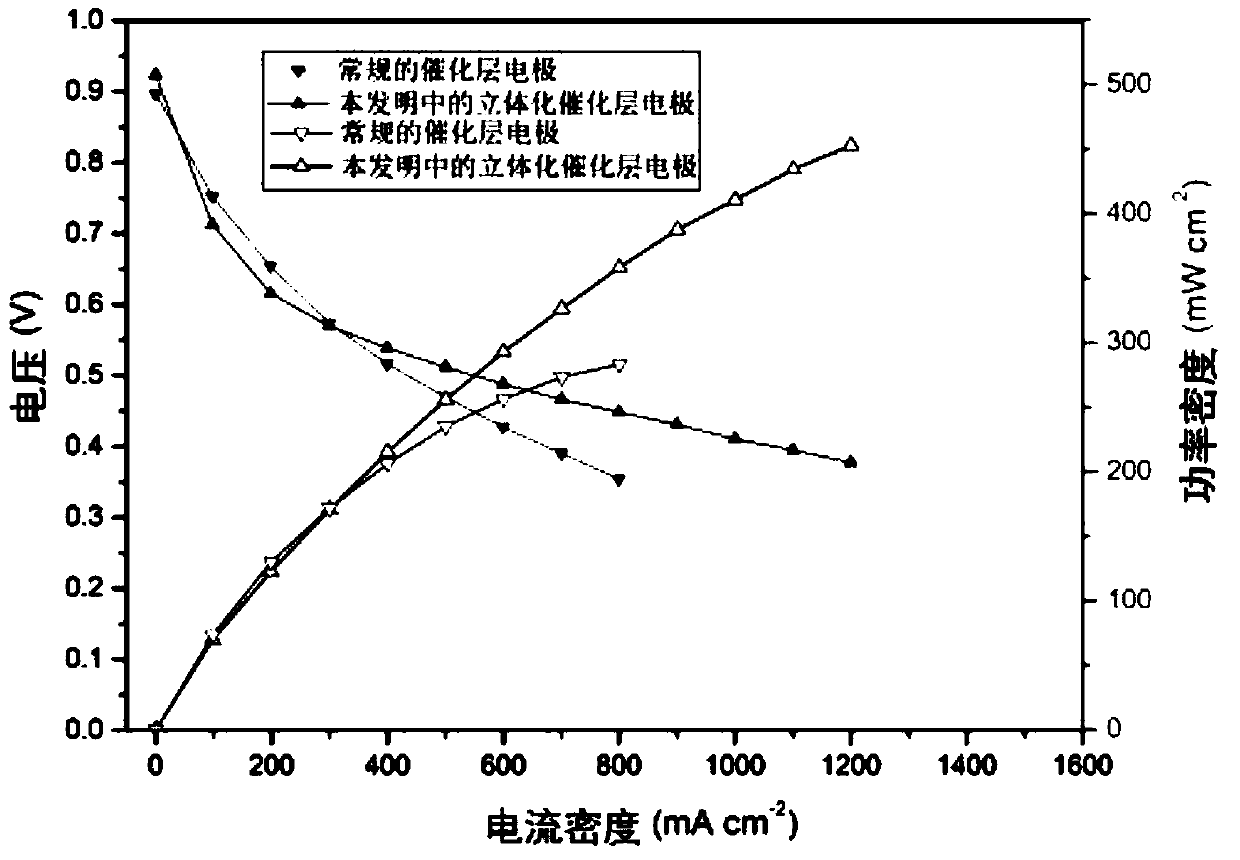
Image

Examples
Embodiment 1
[0026] Take by weighing the Pt / C catalyst of 50mg 40wt.%, wherein 40wt.% refers to that the mass fraction of Pt in the Pt / C catalyst is 40wt.%, 15mg carbon fiber material VGCF-X and 84uL 25wt.% D79, the catalyst loading is 0.267mg / cm 2 , using ethanol as a solvent for ultrasonic dispersion treatment for 0.5h, the solid content of the prepared prefabricated slurry is 5wt.%;
[0027] Take a piece of clean proton exchange membrane with an area of 50cm 2 , using the ultrasonic spraying method to uniformly coat the above-mentioned fully dispersed prefabricated slurry on the proton exchange membrane;
[0028] After the coating is finished, it is placed on a hot table to air-dry for 2 hours; after the drying treatment, the three-dimensional catalytic layer electrode is obtained.
Embodiment 2
[0030] Weigh 100mg 50wt.% PtCo / C catalyst, 40mg carbon fiber material VGCF-H and 450uL5wt.% D520, the catalyst loading is 0.384mg / cm 2 , using a mixed solution of 50% ethanol and 50% isopropanol as a solvent to disperse, the solid content of the prepared prefabricated slurry is 10wt.%, ultrasonic and mechanical stirring and dispersing are each treated for 0.5h;
[0031] Take a piece of clean proton exchange membrane with an area of 100cm 2 , uniformly coating the above-mentioned fully dispersed prefabricated slurry on the gas diffusion layer by a knife coating method;
[0032] After the coating is finished, it is placed in a vacuum oven for drying treatment, the treatment time is 4 hours, and the treatment temperature is 60° C.; after the drying treatment, the three-dimensional catalytic layer electrode is obtained.
Embodiment 3
[0034] Weigh 100mg 50wt.% PtNi / C catalyst, 4mg multi-walled carbon nanotube material and 450uL 5wt.% D520, the catalyst loading is 0.455mg / cm 2 , using n-propanol as a solvent for dispersion, the solid content of the prepared prefabricated slurry is 12wt.%, ultrasonically dispersed for 0.5h, and then mechanically stirred for 1h;
[0035] Take a clean base material (such as PTFE film) with an area of 100cm 2 , using the slit coating method to uniformly coat the above-mentioned fully dispersed prefabricated slurry on the PTFE film;
[0036] Then heat-compress the PTFE film coated with the catalyst layer with a clean proton exchange membrane. The heat-compression treatment temperature is 120°C, the pressure is 0.05MPa, and the time is 5min; after the treatment, the PTFE film is removed. , performing natural air-drying treatment on the prepared catalyst coating film to obtain the three-dimensional catalytic layer electrode;
[0037] After the coating is finished, it is place...
PUM
| Property | Measurement | Unit |
|---|---|---|
| Thickness | aaaaa | aaaaa |
Abstract
Description
Claims
Application Information