
A pulverized coal preheating decoupling combustion device

A combustion device and pulverized coal technology, which is applied in the direction of combustion method, combustion equipment, block/powder fuel preparation, etc., can solve the problems of ineffective coal combustion, inability to effectively suppress, and influence on combustion stability, etc.

Active Publication Date: 2021-04-20
XI AN JIAOTONG UNIV
View PDF15 Cites 0 Cited by
  • Summary
  • Abstract
  • Description
  • Claims
  • Application Information

AI Technical Summary

Problems solved by technology

Chinese Patent Announcement No. "CN102297425B" discloses "a pulverized coal decoupling burner and its decoupling combustion method", which uses the idea of ​​decoupling combustion to invent a pulverized coal decoupling combustion burner and a The combustion method of decoupled combustion, through inertial separation and powder collection to stabilize the flame, divides the pulverized coal into three strands with uneven concentration, and sends them into the furnace from thick to light respectively to achieve the conditions of decoupled combustion, thereby suppressing NO x formation, but the stability of combustion will be affected, and with the addition of oxygen, NO x The formation of the still cannot be effectively suppressed
[0006] Chinese Patent Publication No. "CN205090371U" discloses "a high-efficiency and clean combustion device", which uses the idea of ​​decoupling combustion to divide the combustion process of coal into two processes: gas combustion and coke combustion, and separate them in the gas combustion chamber. Combustion with coke combustion chamber, but the combustion device is mainly aimed at the combustion of coal or briquette, and the combustion method is a fixed bed burner placed on the grate for combustion, which cannot effectively solve the problem of pulverized coal combustion

Method used


Image

  • A pulverized coal preheating decoupling combustion device

Examples


Embodiment Construction

[0031] The present invention will be described in further detail below in conjunction with the accompanying drawings and specific embodiments.

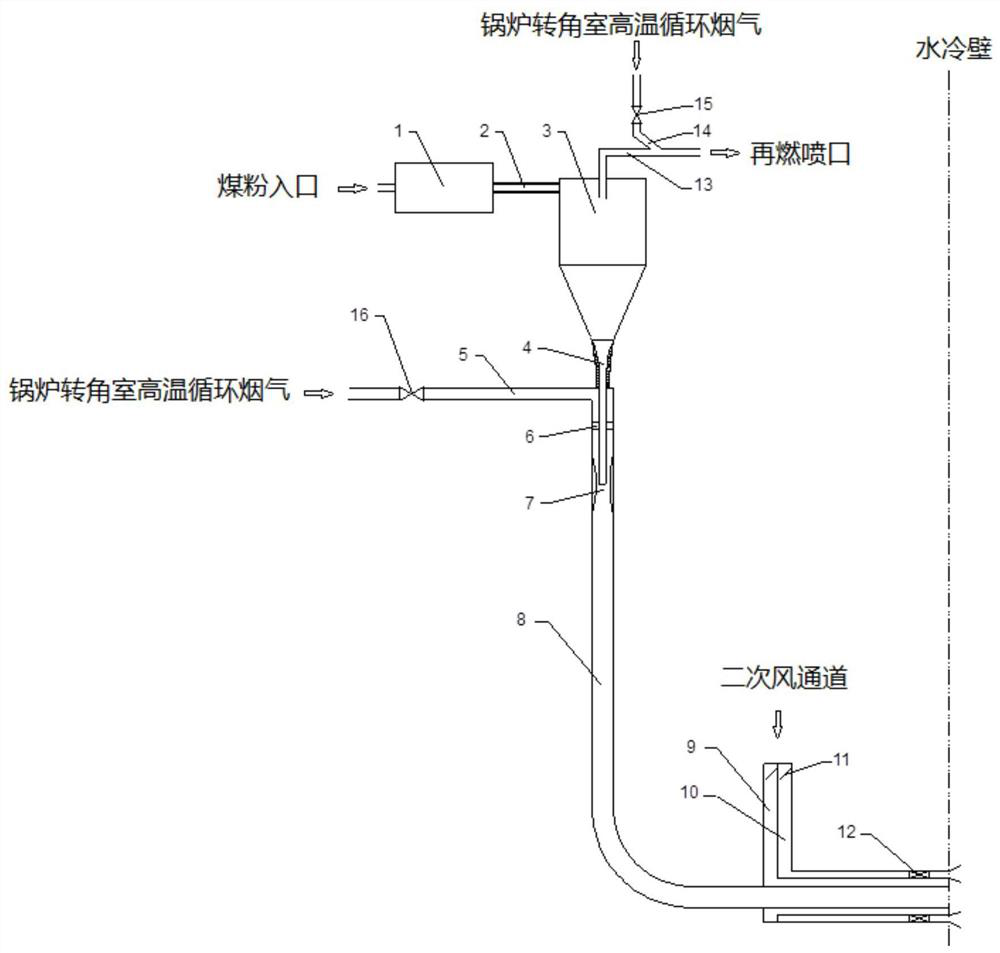
[0032] see figure 1 , a kind of pulverized coal preheating decoupling decoupling combustion device of the present invention, comprises: pyrolysis chamber 1, cyclone separator 3, recirculation flue gas injection device and coke burner connected by flue gas pipe section; The directions are pyrolysis chamber 1, cyclone separator 3, feeding pipe 4, injection nozzle 7 and primary air pipe 8 in sequence.

[0033] The outlet of the pulverized coal high temperature pyrolysis chamber 1 is connected to the upper inlet of the cyclone separator 3 through the pyrolysis product transport channel 2 . The outlet for collecting particles at the lower end of the cyclone separator 3 is connected to the feeding pipe 4, and the gas phase outlet at the upper end is connected to the reburning fuel pipeline 13; the feeding pipe 4 is placed vertically, and t...


PUM


Abstract

The invention discloses a coal powder preheating decoupling decoupling combustion device, comprising: a pyrolysis chamber, a cyclone separator, an injection device and a particle combustion device; the pyrolysis chamber is provided with a raw material inlet and a product outlet; the cyclone separator is provided with Product inlet, volatile matter outlet and particle outlet; the product inlet of the cyclone separator is connected with the product outlet of the pyrolysis chamber through the pyrolysis product transport channel; the volatile matter outlet of the cyclone separator is provided with a reburning fuel pipeline; the cyclone separator A feeding pipe is provided at the particle outlet; the reburning fuel pipe is used to lead into the furnace; the feeding pipe is connected with the particle combustion device through the injection device; the injection device has an ejection air flow; the particle combustion device includes an air duct; The air duct is used to lead into the furnace. The pulverized coal preheating decoupling decoupling combustion device of the present invention is based on the decoupling idea, is suitable for decoupling combustion of pulverized coal, can obtain a higher combustion rate of pulverized coal, has relatively good combustion stability, and can effectively suppress NO x generation.

Description

technical field [0001] The invention belongs to the technical field of pulverized coal combustion equipment, in particular to a pulverized coal preheating, decoupling and decoupling combustion device. Background technique [0002] In the actual engineering case of burning pulverized coal, NO x Emissions and pulverized coal burnout have always been two factors that restrict each other. The burnout rate of pulverized coal increases with the combustion temperature and oxygen concentration in the combustion stage, but the high temperature and oxygen-enriched combustion conditions will greatly promote the NO x On the contrary, if the temperature and oxygen concentration in the combustion stage are reduced, although the NO in the combustion stage can be suppressed x However, the ignition stability of pulverized coal is affected, and the burnout rate is reduced, and the carbon content of fly ash and slag of pulverized coal will increase. Therefore, in achieving low NO x It has ...

Claims


Application Information

Patent Timeline
Patent Type & Authority Patents(China)
IPC IPC(8): F23C9/06F23K1/04F23L9/00F23L17/16
CPCF23C9/06F23K1/04F23L9/00F23L17/16
Inventor 王学斌许鑫玮张兰谭厚章刘兴刘鹤欣
Owner XI AN JIAOTONG UNIV
Learn More